crwdns2915892:0crwdne2915892:0
During this guide you will be required to unsolder an LED from a PCB and then solder the new LED onto the same connection points.
crwdns2942213:0crwdne2942213:0
-
-
Insert the flat tip of the metal spudger into the seam between the back panel and the screen.
-
Slide the spudger across the perimeter of the device and gently pry apart at each corner.
-
After the pressure clamps are released orient the device so that the speaker is to the right and the screen is tilted away from you.
 crwdns2952109:0crwdne2952109:0
-
-
-
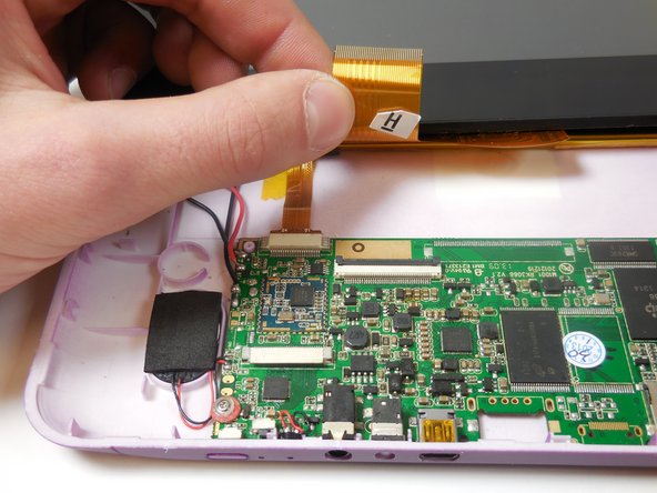
Locate the shorter ribbon cable and the black pressure tabs that hold the ribbon cable in place.
-
Use the plastic spudger to gently slide the tabs about 2mm away from connector.
-
-
-
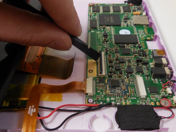
Locate the longer ribbon cable and the pressure clamp that holds the cable in the connection port.
-
Using the plastic spudger, flip the black locking clip up.
-
Once the clip is unlocked, the cable should slide out without resistance
-
-
-
-
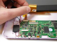
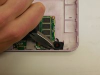
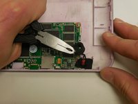
Gently grasp the foam ring with pliers and pull upwards to release the adhesive on the bottom of the ring.
-
-
crwdns2935267:0crwdne2935267:0Tweezers$4.99
-
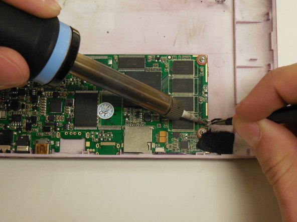
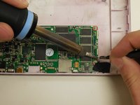
Using a soldering iron apply heat to the connection point between the LED and PCB.
-
When the solder is heated sufficiently (turns liquid and shiny) remove the LED lead with tweezers.
-
Repeat for other connection point.
-
-
-
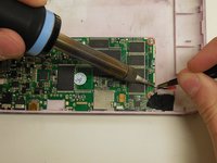
Using a soldering iron apply heat to the connection point where the LED connects to the PCB.
-
When the solder is heated sufficiently (turns liquid and shiny) insert the LED lead with tweezers. If necessary add additional solder to ensure a solid electrical connection.
-
Repeat for the other connection point.
-
-
-
Position the new LED in the same position as the old LED.
-
-
-
Using tweezers or finger, replace the circular foam ring around the new LED.
-


To reassemble your device, follow these instructions in reverse order.
crwdns2935287:0crwdne2935287:0

Colorado Springs, Team 5-2, Panko Spring 2015 crwdns2935289:0Colorado Springs, Team 5-2, Panko Spring 2015crwdne2935289:0
UCCS-PANKO-S15S5G2
crwdns2931471:03crwdne2931471:0
crwdns2935297:08crwdne2935297:0