crwdns2915892:0crwdne2915892:0
This repair guide was authored by the iFixit staff and hasn’t been endorsed by Google. Learn more about our repair guides here.
This guide will teach you how to replace the rear facing camera on your Google Pixel XL. The steps should be easy to follow and tFollow this guide to replace the rear-facing camera module for the Google Pixel XL.
The Pixel XL’s unreinforced display panel is fragile and is attached to the frame with strong adhesive, making repairs difficult. There is a considerable chance of breaking the display, especially if it already has micro-fractures. Be sure to apply plenty of heat and be extremely careful during the prying stage.he rear facing camera will be found on the motherboard of the device.
crwdns2942213:0crwdne2942213:0
-
-
Insert a SIM eject tool, SIM eject bit, or a paperclip into the small hole on the left edge of the phone, near the top.
-
Press to eject the tray.
-
-
-
Heat an iOpener and apply it to the top edge of the display for two minutes.
-
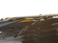
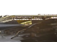
Take note of the following regions before you begin prying:
-
Thin adhesive lined against the display panel
-
Thick adhesive
-
The OLED display panel, which is very prone to damage
-
The display cable, which can be damaged during prying
From my experince, it’s better to use a heat gun (if iFixit sold a good heat gun in volume, they should spruik that). Also, heat ALL sides at the same time BUT concentrate on the top part of the phone where the foam adhesive tape is thickest, second on the bottom where the foam is almost as thick. It also helps to use the 2nd & 3rd images in the series to visualise where the adhesive is.
Ty for the advice I prefer heat gun but my first pixel
-
-
-
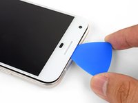
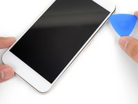
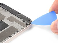
Once the edge is warm to the touch, apply a suction cup close to the edge.
-
Lift on the suction cup, and insert an opening pick into the gap.
-
If you have trouble creating a gap, reheat the edge and try again.
From my experience, I had to use a thin blade (such as the ones included with the deluxe iFixit repair kit) to slide into the small gap, and cut away at the foam adhesive. Once enough of a gap is created, the picks can then be used to push the adhesive aside - but the adhesive is so thick, especially -as Brewmaster396 observed in the comments below - at the top right corner behind the screen, that the knife is required to cut it. I failed here - cracking the back layer of my screen - because I didn’t take time to cut all the adhesive away from that thick part, and kept trying to pull the screen off. It doesn’t take a lot of pressure to crack - so maybe it’s more a thing of cutting and floating the screen up, not pulling and prying.
Mark the picks with lines that show how deep you can go in that part of the screen. This will help keep you from accidentally hitting the fragile screen
Matthew Goodwin - Excellent suggestion.
Jon T made a great suggestion about creating a mark on the picks (see above).
Matthew Goodwin responds with an “Excellent suggestion.”
Here we are 8 months later and no lines on the picks in my new pro-tech tool kit, not sure why this hasn’t been implemented at this point in time.
Bob H.
Thin, but sturdy pieces of paper (playing cards, bits of paper box packaging) helped me a lot when trying to open my screen. The plastic picks are useful, but very slippery so you should use extra caution when applying pressure with those.
-
-
-
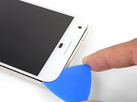
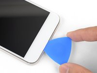
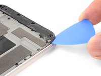
Slide the opening clip across the top edge to slice through the adhesive.
-
Leave an opening pick in the edge to prevent the adhesive from resealing.
-
-
-
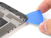
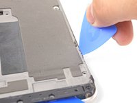
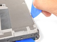
Heat an iOpener and apply it to the right edge of the phone for two minutes.
-
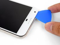
Insert an opening pick near the top edge of the phone, where you have already sliced the adhesive.
-
Slowly guide the pick around the right corner.
-
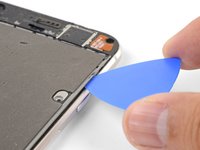
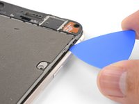
Carefully slide the pick down the right edge of the phone to slice through the adhesive.
-
Repeat the step for the left edge of the phone.
-
-
-
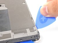
Heat the bottom edge with an iOpener for two minutes.
-
Insert a pick near the right edge where you have already loosened the adhesive.
-
Carefully guide the pick around the corner.
-
Slide the pick along the bottom edge to slice through the adhesive.
-
-
-
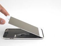
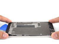
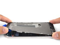
Once you have sliced around the perimeter of the phone, carefully lift the display assembly up slightly by the right corners.
-
Use an opening pick to slice through any remaining adhesive.
As long as you’ve disengaged the adhesive relatively evenly around all sides, I found mounting the suction cup in the middle (biased a little to the left or right side), helps a lot on this step.
do I need to get a screen adhesive when it goes back?
чи потрібно мені купувати клейку плівку для екрану, коли він повернеться назад?
якщо ви відносно рівномірно відокремили клей з усіх боків, я виявив, що встановлення присоски посередині (трохи зміщена вліво або вправо) дуже допомагає на цьому кроці.
-
-
-
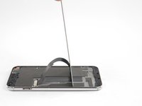
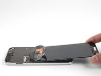
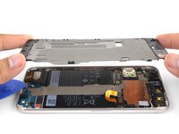
Lift the display assembly from the top end and swing it around such that it rests upside down on the frame.
-
-
crwdns2935267:0crwdne2935267:0Magnetic Project Mat$19.95
-
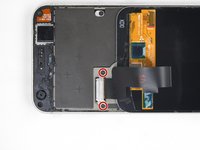
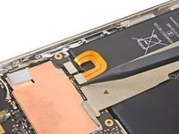
Remove the two 4 mm T5 screws securing the display cable bracket.
-
Remove the display cable bracket.
-
-
-
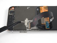
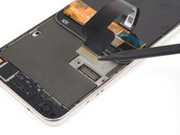
Use the point of a spudger to pry up and disconnect the display cable from its connector.
i have to agree with the comment here about the connector. If you press it in the middle, it will bend. Resulting in either bent pins on the motherboard or the display. In my case it was both !
Be careful prying up the connector and apply force only from the side as shown in the picture cause in the longest side there are capacitors that can be broke doing the lever ( happened to me Repair missing capacitor near display connection port )
мушу погодитися з коментарем щодо роз'єму. якщо натиснути на нього посередині, він зігнеться. в результаті зігнуться або контакти на материнській платі, або на дисплеї. у моєму випадку це було і те, й інше!
будьте обережні, піднімаючи роз'єм, і застосовуйте силу лише збоку, як показано на малюнку, оскільки на найдовшому боці є конденсатори, які можна зламати, потягнувши за важіль (зі мною це сталося. ремонтуйте відсутній конденсатор біля порту підключення дисплея ).
-
-
crwdns2935267:0crwdne2935267:0Tweezers$4.99
-
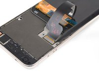
Remove the display assembly.
The Parts List does not state you need a replacement display. Is this portion of the Repair Guide copied and pasted from another guide (perhaps the screen replacement guide) or will I need to procure a replacement screen before I attempt to replace the battery?
It is possible to replace the battery without replacing the display, but there is a significant chance you may break the display during removal. It depends on if your display already has micro-fractures, and how stubborn the screen adhesives are. I would personally buy a screen just in case, and return the part if I didn’t need it.
Hello, I recently bought a refurb screen off of eBay to fit. The phone was 100% working before and just needed a new display/battery.
The battery came before the display. I wanted to test the display before doing too much reassembly, so I plugged in the battery, connected the mother/daughter boards with the interconnect cable, and then plugged in the LCD.
When I press the power button there is the usual single buzz from booting, but the display is completely blank.
Is the replacement screen DOA, or are there important traces/connections made by fully assembling the midframe and missing screws before testing the LCD?
If I already have all the ingredients for a fair test of the LCD, then it seems the LCD is bad?
Like I said the phone worked perfectly before… and if the new battery is dead, I would expect no buzz, or at least a battery graphic?
Hi John,
If the phone buzzed, that usually signifies that it has booted up—having no image at that point usually means some kind of display issue. I would suggest disconnecting the display connector, carefully checking for any debris in the socket, and carefully re-connecting it.
I’ve also seen a comment in another Pixel guide that suggests plugging in the display connector before the battery. If that works, please leave a comment!
battery connector is not accessible without removing the display first………. and reassembling, battery has to be connected first, then the plastic piece and then the display
-
-
-
-
Remove the following screws that secure the midframe to the back:
-
Seven black 4 mm T5 screws
-
Two silver 3 mm T5 screws
-
-
-
The midframe is held tightly in place by plastic clips which push into the edge of the back case.
-
-
-
Find the small notch in the bottom left corner of the frame and insert an opening pick.
-
Slide the opening pick along the bottom edge of the phone towards the bottom right corner and leave it there.
This step was impossible on my phone as a gap could not be formed at the notch to pry the corner up using either pick or playing card . Flathead micro screwdriver was required causing insignificant cosmetic damage at that area.
This step takes a few tries, starting with the pick perpendicular to the phone. Eventually, after gentle prying, it will catch the corner so you can slip the pick underneath. Like everything in this repair, it requires you to be exceedingly delicate and patient.
Take the tip of the tweezers, insert it in the screw hole near where they show to insert the pick and gently pry up. You should be able to move the plate upwards enough to insert the pick
-
-
-
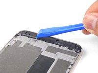
Insert a separate opening pick into the right edge of the phone, near the bottom.
-
Slowly push the pick upwards along the seam until the first clip pops free.
-
Once you've released the clip, leave the opening pick in place to prevent the midframe from resealing.
I found that leaving the pick in the middle, and using it as a lever (think like bending a pipe over one’s knee and the pick in the middle is the knee) to “pop” the top edge up helped a lot more than trying to use more picks to pry this mid layer up…
-
-
-
Insert an opening pick into the right edge of the phone and slide it upwards towards the top right clip.
-
Slowly slide the pick past the clip to disengage it from the frame.
-
-
-
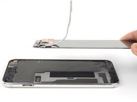
Grasp the right edge of the midframe by the corners and slowly hinge the edge up.
-
When the left edge feels loose, stop hinging and lift the midframe upwards.
-
Remove the midframe.
-
-
-
Use the point of a spudger to pry up and disconnect the battery connector.
-
Bend the battery flex cable slightly so that it will not accidentally touch the motherboard.
-
-
-
Use the point of a spudger to pry up and disconnect the button strip connector.
-
-
crwdns2935267:0crwdne2935267:0Tweezers$4.99
-
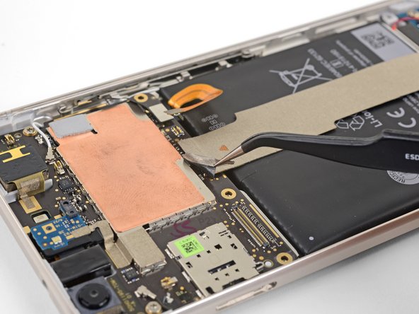
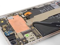
Use tweezers to peel up the tape at the top of the interconnect cable.
-
-
-
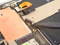
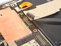
Use the point of a spudger to pry up and disconnect the interconnect cable from the motherboard.
-
-
-
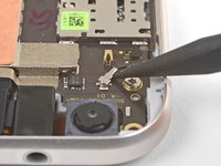
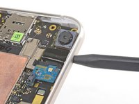
Use the point of a spudger to disconnect the black antenna cable from the motherboard, near the front facing camera module.
-
Route the antenna cable out of its retaining clip.
-
-
-
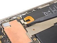
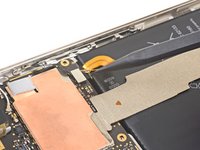
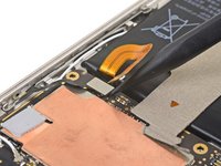
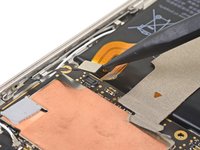
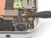
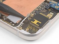
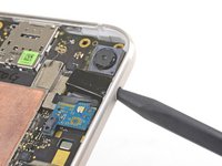
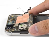
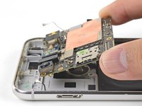
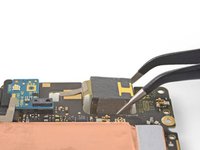
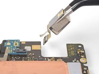
Use the point of a spudger to pry up and disconnect the white antenna cable from the motherboard, near the rear facing camera module.
-
Route the antenna cable out of its retaining clip.
What connector is this? I just broke the connector off the board instead of just disconnecting it. What did I just loose the ability to do?
Update: I pulled the broken connector off the cable, put everything back together, leaving the cable just sandwiched in the right place, and everything seems to be still working completely. Wifi, 4G, Bluetooth.. time will tell what is broken… but it’s not immediately noticeable… I feel really lucky!
David -
Hi jeffersdavid93, did you ever figure out what stopped working with this connector? Thanks!
-
-
-
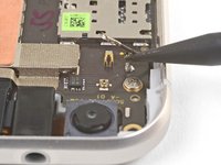
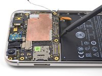
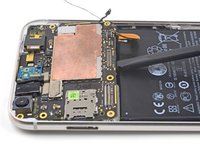
Remove the two 3 mm T5 screws securing the motherboard to the frame.
-
-
-
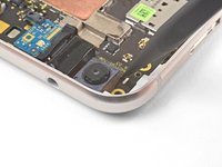
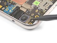
Use the point of a spudger to pry up and loosen the front facing camera module from its socket.
-
-
-
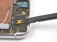
Insert the point of a spudger into the headphone jack port and pry upwards to loosen the port from its socket.
-
-
-
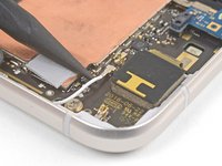
Use the flat end of a spudger to pry the bottom edge of the motherboard up slightly, loosening it from its recess.
-
-
-
Locate the fingerprint sensor cable attached to the underside of the motherboard, near the bottom edge.
-
Use the point of a spudger to pry and release the fingerprint sensor cable from its socket.
-
Peel the cable away from the motherboard.
-
-
-
Hold the motherboard by the corners and maneuver it out of its recess, being careful not to snag any cables.
-
Bend the fingerprint sensor cable slightly so that it bows upward near the connector.
-
Stand the motherboard up and position it such that the connector rests against the socket.
-
Use your finger to carefully align the connector and press it into the socket. Do not use excessive force! If done correctly, the socket should hold the connector securely.
-
-
-
Flip the motherboard such that the underside is facing up.
-
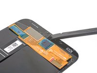
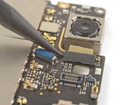
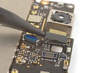
Use the point of a spudger to pry up and disconnect the rear facing camera connector from its socket.
There was a small blue daughter board that was required to be removed for me to access the rear facing camera seat. A minor step, but it surprised me when it popped off.
-
-
-
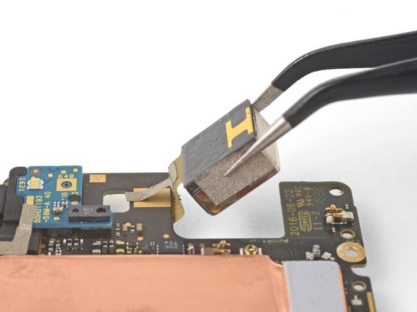
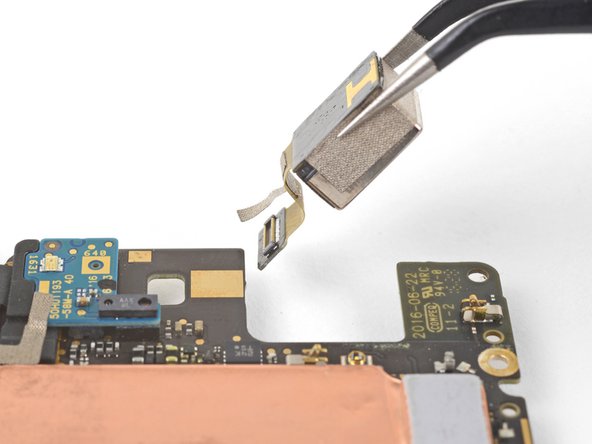
Flip the motherboard such that the backside is facing down.
-
Pivot the camera module out of its recess and slowly pull it out, lifting the adhesive tape in the process.
-
Remove the rear camera module.
-


To reassemble your device, follow these instructions in reverse order.
Repair didn’t go as planned? Check out our Google Pixel XL Answers community for troubleshooting help.
To reassemble your device, follow these instructions in reverse order.
Repair didn’t go as planned? Check out our Google Pixel XL Answers community for troubleshooting help.
crwdns2935221:0crwdne2935221:0
crwdns2935229:06crwdne2935229:0

crwdns2947412:05crwdne2947412:0
Where can I get the replacement camera
https://www.witrigs.com/oem-rear-camera-...
This is one of other only places I could find to get a replacement camera module.
iFixit sells the replacement part here. It looks like new camera modules are out of stock, but used and fully tested ones are still in stock as of May 15, 2018.
A helpful tip: before you re-assemble the phone, shine a bright light through the back glass and check that there is no dust or debris on the inside of the back glass or the camera lens.
Also, this may be obvious to some, but you will need replacement adhesive for the display in order to re-attach it to the phone. I didn’t even think about this until I had already started the repair and taken the display off.
Do you think that if I put a Pixel 3 camera in there, it would still work?
Have any of you tried to up the storage capacity on one of these things?