crwdns2931315:0crwdnd2931315:0crwdne2931315:0
crwdns2942213:0crwdne2942213:0
-
crwdns2935201:0crwdne2935201:0 crwdns2935203:0crwdne2935203:0
-
Insert a SIM eject tool, bit, or a straightened paper clip into the small hole on the SIM card tray on the left edge of the phone.
-
Press firmly to eject the tray.
-
Remove the SIM card tray.
-
-
crwdns2935201:0crwdne2935201:0 crwdns2935203:0crwdne2935203:0
-
Prepare an iOpener and apply it to the bottom edge of the back panel for one minute.
-
-
crwdns2935201:0crwdne2935201:0 crwdns2935203:0crwdne2935203:0
-
Apply a suction cup to the heated edge of the back panel by pressing down on it to create suction, as close to the edge as possible.
-
-
crwdns2935201:0crwdne2935201:0 crwdns2935203:0crwdne2935203:0
-
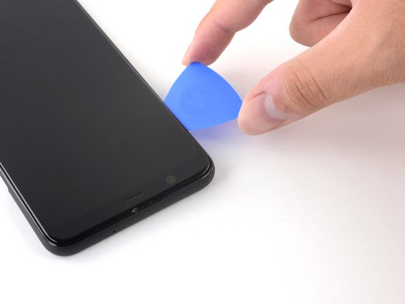
Pull up on the suction cup with strong, steady force to create a gap between the back panel and the frame.
-
Insert the point of an opening pick into the gap.
-
-
crwdns2935201:0crwdne2935201:0 crwdns2935203:0crwdne2935203:0
-
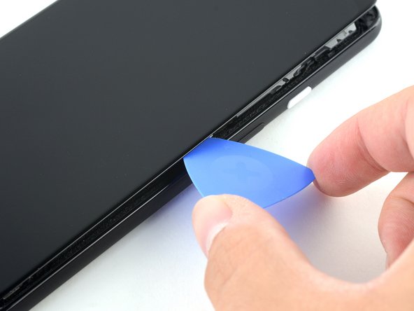
Slide the opening pick across the bottom towards the left corner to slice the adhesive.
-
With the pick still inserted, slide it from the bottom left corner over to the bottom right corner to completely slice the bottom side adhesive.
-
Leave the pick inserted in the bottom right corner to prevent the adhesive from re-sealing.
-
-
crwdns2935201:0crwdne2935201:0 crwdns2935203:0crwdne2935203:0
-
Prepare an iOpener and apply it on the left edge of the phone for one minute.
-
-
crwdns2935201:0crwdne2935201:0 crwdns2935203:0crwdne2935203:0
-
Insert a second opening pick underneath the back panel directly over the charge port.
-
Slide the opening pick to the bottom left corner of the phone.
-
-
crwdns2935201:0crwdne2935201:0 crwdns2935203:0crwdne2935203:0
-
Slide the opening pick around the bottom left corner and across the left side of the phone to slice the adhesive.
-
Stop when you reach the top left corner, near the camera, and leave the pick inserted.
-
-
crwdns2935201:0crwdne2935201:0 crwdns2935203:0crwdne2935203:0
-
Prepare an iOpener and apply it on the right edge of the phone for one minute.
-
-
crwdns2935201:0crwdne2935201:0 crwdns2935203:0crwdne2935203:0
-
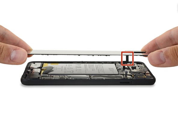
With the first two opening picks still in place, insert a third pick on the lower part of the righthand side.
-
Slide the opening pick up towards the top of the phone, slicing the right side's adhesive.
-
Stop when you reach the top right corner, and leave the pick inserted.
-
-
crwdns2935201:0crwdne2935201:0 crwdns2935203:0crwdne2935203:0
-
Slide the third opening pick around the top right corner and across the top side of the phone, slicing the final strip of adhesive.
-
-
crwdns2935201:0crwdne2935201:0 crwdns2935203:0crwdne2935203:0
-
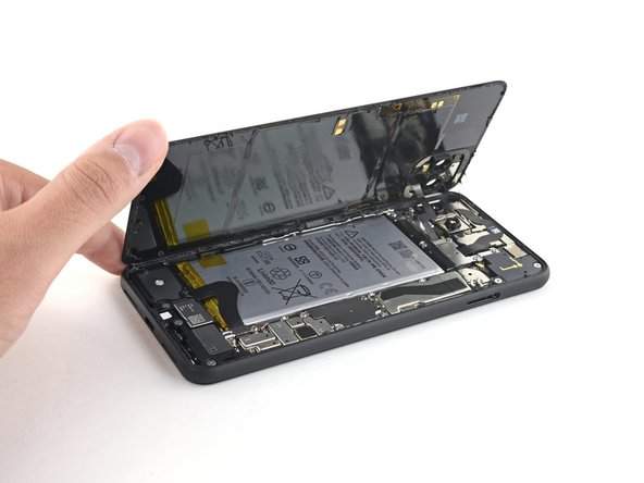
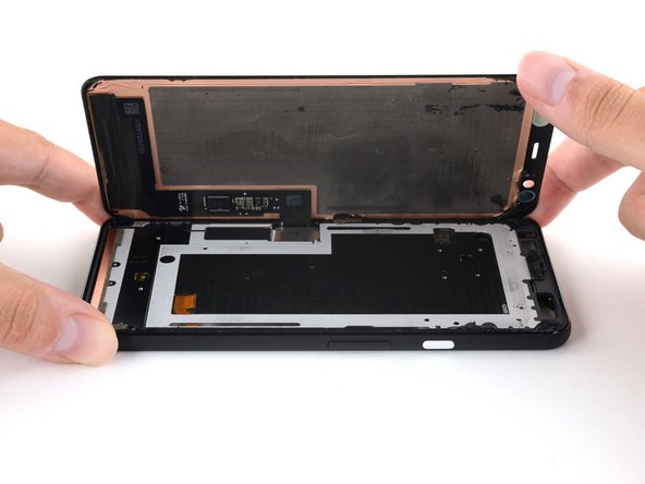
Once you have sliced around the perimeter of the phone, carefully lift the right edge of the back cover, opening it like a book.
-
Do not try to pull the panel all the way off yet, as it is still connected to the phone.
-
-
crwdns2935201:0crwdne2935201:0 crwdns2935203:0crwdne2935203:0
-
Continue swinging open the back panel until you can rest it on the left edge the phone, being careful not to put any stress on the attached ribbon cable.
-
-
crwdns2935201:0crwdne2935201:0 crwdns2935203:0crwdne2935203:0
-
Remove the four T3 Torx screws securing the battery connector shield:
-
One 1.8 mm screw
-
One 4.1 mm screw
-
One 4.4 mm shouldered screw
-
One 4.0 mm shouldered screw
-
-
-
crwdns2935201:0crwdne2935201:0 crwdns2935203:0crwdne2935203:0
-
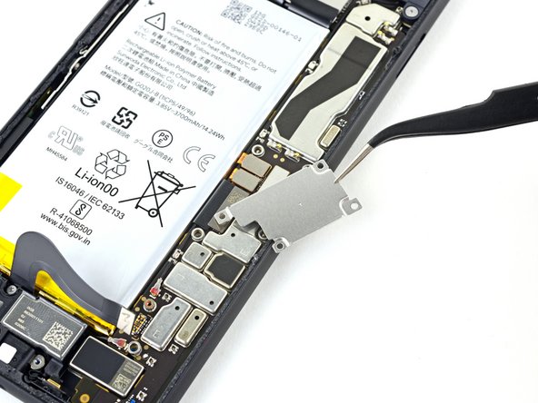
Use a pair of tweezers to remove the battery connector shield.
-
-
crwdns2935201:0crwdne2935201:0 crwdns2935203:0crwdne2935203:0
-
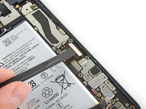
Using the pointed end of a spudger, pry the battery connector straight up from the motherboard to disconnect the battery.
-
-
crwdns2935201:0crwdne2935201:0 crwdns2935203:0crwdne2935203:0
-
Using the flat end of a spudger, gently fold the battery cable over so it doesn't accidentally make contact during the rest of your repairs.
-
-
crwdns2935201:0crwdne2935201:0 crwdns2935203:0crwdne2935203:0
-
Use a T3 Torx driver to remove the two 4.1 mm screws securing the back panel connector cover.
-
-
crwdns2935201:0crwdne2935201:0 crwdns2935203:0crwdne2935203:0
-
Use a pair of tweezers to remove the back panel connector cover.
-
-
crwdns2935201:0crwdne2935201:0 crwdns2935203:0crwdne2935203:0
-
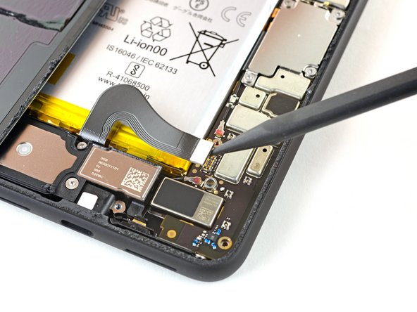
Using the pointed end of a spudger, pry up and disconnect the back panel connector.
-
-
crwdns2935201:0crwdne2935201:0 crwdns2935203:0crwdne2935203:0
-
Gently pry back the battery adhesive pull tab to allow easier access to the screws underneath it.
-
-
crwdns2935201:0crwdne2935201:0 crwdns2935203:0crwdne2935203:0
-
Remove the three T3 Torx screws securing the rear-facing camera connector cover:
-
One 2.7 mm screw
-
One 4.1 mm screw
-
One 4.2 mm screw
-
-
crwdns2935201:0crwdne2935201:0 crwdns2935203:0crwdne2935203:0
-
Use a pair of tweezers to remove the rear-facing camera connector cover.
-
-
crwdns2935201:0crwdne2935201:0 crwdns2935203:0crwdne2935203:0
-
Remove the three T3 Torx screws securing the front-facing camera connector cover:
-
One 4.1 mm screw
-
One 4.0 mm shouldered screw
-
One 4.1 mm shouldered screw
-
-
crwdns2935201:0crwdne2935201:0 crwdns2935203:0crwdne2935203:0
-
Use a pair of tweezers to remove the front-facing camera connector cover.
-
-
crwdns2935201:0crwdne2935201:0 crwdns2935203:0crwdne2935203:0
-
Using the pointed end of a spudger, pry the camera and sensor connectors straight up from the motherboard.
-
-
crwdns2935201:0crwdne2935201:0 crwdns2935203:0crwdne2935203:0
-
Disconnect the additional sensor connector.
-
-
crwdns2935201:0crwdne2935201:0 crwdns2935203:0crwdne2935203:0
-
Remove the three T3 Torx screws securing the front camera and sensor assembly:
-
Two 2.7 mm screws
-
One 3.1 mm screw
-
-
crwdns2935201:0crwdne2935201:0 crwdns2935203:0crwdne2935203:0
-
Use a pair of tweezers to remove the front camera and sensor assembly.
-
-
crwdns2935201:0crwdne2935201:0 crwdns2935203:0crwdne2935203:0
-
Use a T3 Torx driver to remove the four 3.5 mm screws securing the display connector cover.
-
-
crwdns2935201:0crwdne2935201:0 crwdns2935203:0crwdne2935203:0
-
Use a pair of tweezers to remove the display connector cover.
-
-
crwdns2935201:0crwdne2935201:0 crwdns2935203:0crwdne2935203:0
-
Use the flat end of a spudger to disconnect the display connector from the motherboard.
-
-
crwdns2935201:0crwdne2935201:0 crwdns2935203:0crwdne2935203:0
-
Prepare an iOpener and apply it to the right edge of the display near the power button for one minute.
-
-
crwdns2935201:0crwdne2935201:0 crwdns2935203:0crwdne2935203:0
-
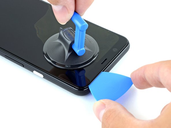
Apply a suction cup to the heated edge of the display assembly.
-
Pull up on the suction cup with strong, steady force to create a gap between the display assembly and the frame.
-
Insert the point of an opening pick into the gap.
-
-
crwdns2935201:0crwdne2935201:0 crwdns2935203:0crwdne2935203:0
-
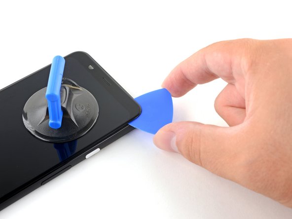
Slide the opening pick down the right bezel of the phone, between the display and the frame, to slice the adhesive.
-
Leave the pick inserted in the bottom right corner.
-
-
crwdns2935201:0crwdne2935201:0 crwdns2935203:0crwdne2935203:0
-
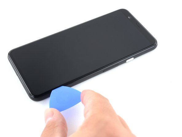
Insert a second opening pick underneath the display assembly in the top left corner of the phone, near the front-facing camera cutout.
-
Slide the opening pick around the corner and down the left side of the phone, stopping about halfway down, and leave the pick inserted.
-
-
crwdns2935201:0crwdne2935201:0 crwdns2935203:0crwdne2935203:0
-
Insert a third opening pick under the display assembly in the middle of the right edge of the phone and twist to separate the assembly.
-
-
crwdns2935201:0crwdne2935201:0 crwdns2935203:0crwdne2935203:0
-
Tilt the display assembly up along the left edge of the phone.
-
-
crwdns2935201:0crwdne2935201:0 crwdns2935203:0crwdne2935203:0
-
Slide the display connector out of the hole near the motherboard to separate the display assembly from the rest of the phone.
-
-
crwdns2935201:0crwdne2935201:0 crwdns2935203:0crwdne2935203:0
-
Remove the display assembly.
-
Be sure to test your repairs before you affix the display assembly with adhesives.
-


crwdns2935221:0crwdne2935221:0
crwdns2935229:021crwdne2935229:0


crwdns2944067:010crwdne2944067:0
If you’re only replacing the screen, can you just skip to Step 34?
Because the front-facing camera module is partially embedded in the screen, it’s recommended that you remove it before attempting a screen repair. You won’t have to worry about damaging or realigning the module during reassembly!
Hi, I bought an OEM screen to replace my broken one: how can I make sure the OEM replacement is an original one and not simply a comaptible screen of lower quality?
If I'm only replacing the front screen which steps do I need to do and which can I skip?
The Pixel 4 XL’s layout requires the rear panel to be removed in order to disconnect the display connector, which is necessary to do prior to removing & replacing the display. This guide is that entire process, so no steps should be skipped. Happy fixing!