crwdns2915892:0crwdne2915892:0
If the pictures or video are fuzzy or unable to focus, the lens may need replacement. Follow this guide to do so.
crwdns2942213:0crwdne2942213:0
-
crwdns2935267:0crwdne2935267:0Tweezers$4.99
-
Remove the faceplate by carefully prying around the edge using a plastic opening tool. Loosen the clips on the edge, then pull the faceplate off.
-
Use the tweezers to lift the faceplate from the rest of the device.
-
-
-
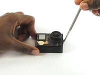
Using a #00 Phillips head screwdriver, remove the following screws:
-
One 4.6 mm screw
-
Three 8.2 mm screws
-
Two 6.1 mm screws
Any more detailed specs on these screws available? Need to but a replacement set, where to buy? How can I find them, size of the head, and the depth etc! Thanks!!
Please note the 4.6 mm screw goes aver the battery door not next to the screen.
+1 on the 4.6mm screw being bottom left not top left
´+1, broke my shell because of this.
There is absolutely no need to remove those 2 screws under the lens… -.-
-
-
-
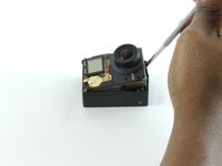
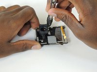
Insert a metal spudger between the back plastic housing and the camera board assembly. Working around the edge to be careful of the inner components, carefully remove the camera.
-
-
-
-
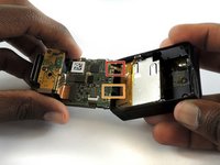
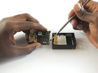
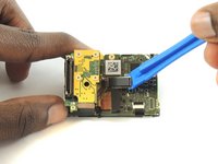
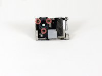
Using tweezers, remove the ribbon strip by pulling on it. This will remove the connection.
-
Push down on the three wires with the metal spudger and the clip will disconnect from the motherboard.
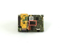
Removing the tiny gold ribbon strip and the wires from the right hand side as shown in the image is an unnecessary step to change out the lens. In fact it is recommendable to NOT remove these, especially the gold ribbon strip that is shown in the red box. It is very difficult to get this ZIF cable back in place once it has been removed. Simply open the camera carefully so as not to pull on this cable and the wires and proceed with the other steps.
I agree that the 2 cables shown above do NOT need to be removed in order to replace the image sensor. Just keep the internal assembly (circuit boards) close to the black housing and at a 90 degree angle. Don’t put any strain on the cables though! You can still access the 4 screws holding the sensor board in place as well as pull up the connector attaching the sensor to the mainboard. You’ll save a lot of time (and headache) by leaving those cables attached.
If you are having trouble connecting the Ribbon cable in particular, use tape to hold buttons in place, remove battery housing & connect the cables up to the battery housing. Then carefully reinsert the battery housing, lay the motherboard down on the casing slightly overhanging the socket end to get to the screw holes.
Oh my god ! this ribbon strip is the devil ! I turn mad !!!!!!!
those ribbon-ports have a lever to release and secure ribbon. DO NOT PULL directly nor insert ribbons without pulling levers up. once they are on right place, push levers down again (one for each ribbon)
I failed on reinserting the ribbon cable here. The “ZIF” port under the LCD was seemingly glued shut, and I ended up damaging the cable trying to reinsert it. I recommend trying one of the approaches above, including leaving these cables connected or removing the battery module from the case to make this step easier.
-
-
-
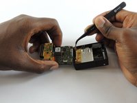
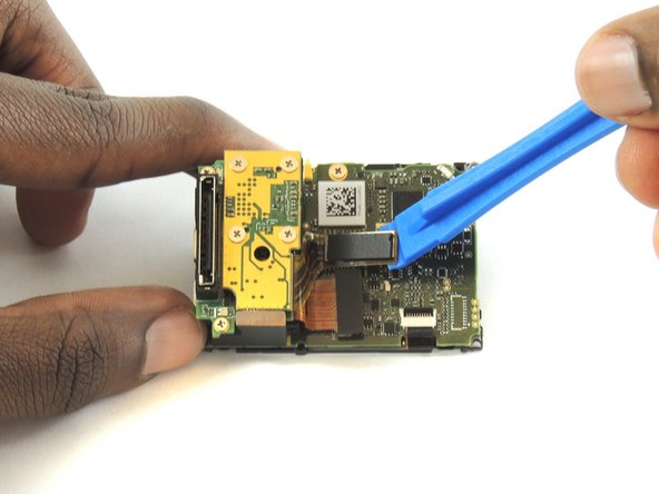
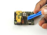
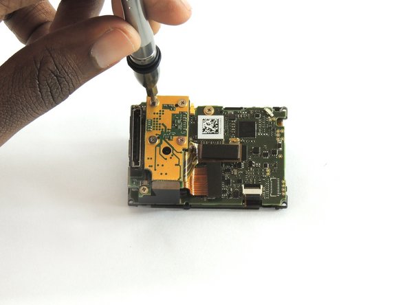
Using a plastic opening tool, separate the camera sensor's connector from the motherboard.
-
-
-
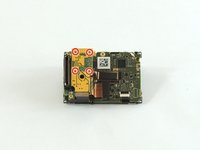
Using a #00 Phillips head screwdriver, remove the four 3.0mm screws holding the camera sensor.
good job!
only it’s unnecessary to unscrew the couple of 6.1 mm screws of yellow circles in this kind of fixing, but dissipator remain in position, with another screw on the other side.
-
-
-
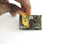
Using a #00 Phillips head screwdriver, remove the following screws:
-
Three 2 mm screw
-
-
-
Lift the lens from the front housing.
-


To reassemble your device, follow these instructions in reverse order.
To reassemble your device, follow these instructions in reverse order.
crwdns2935221:0crwdne2935221:0
crwdns2935229:05crwdne2935229:0
crwdns2915084:0crwdne2915084:0

USF Tampa, Team S2-G1, Sullivan Spring 2017 crwdns2935289:0USF Tampa, Team S2-G1, Sullivan Spring 2017crwdne2935289:0
USFT-SULLIVAN-S17S2G1
crwdns2931471:04crwdne2931471:0
crwdns2935297:012crwdne2935297:0
crwdns2947410:01crwdne2947410:0
Between step 6 and step 7, you skipped a really important step…