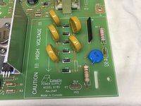
crwdns2915892:0crwdne2915892:0
After what I suspect was a power surge a while back, my nice $450 electrostatic air cleaner became non-functioning, I was determine to find out why. I have to give GeneralAire credit, they actually have a usable troubleshooting section of their manual to help isolate functions and problems, and a part list to identify things, unfortunately the parts that needed replacement were more than an entire new unit… so I dug in a little deeper.
crwdns2942213:0crwdne2942213:0
-
-
The first was to test the front panel LED indicator to rule out stupidity, but I had a good idea it went well beyond an indicator light as the filter had not been getting dirty.
-
This was a simple test, touch a 9V battery in the correct polarity to the red and black wires coming off the HV board, the indicator should light up brightly, and it did.
-
-
-
Making sure the yellow and blue wires from the 24VAC transformer are off the HV board, clip on a volt meter and energize the unit with the front panel switch. I should have seen voltage there for about 5 seconds as the air proving switch turned on then off, but got nothing.
-
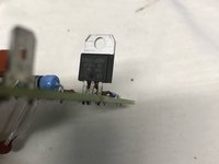
Per the manual, I moved back to the air proving switch, a small board with a PTC thermistor and a triac that energize to provide 120VAC to transformer. With output lead 4 disconnected, connect he volt meter between pin 1 and 4.
-
Energize the unit once again. Still only a few 100mV. Carefully check that there is 120VAC on the incoming posts 2 & 3, yep it's there.
-
-
-
-
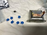
At this point, I had three suspects, the transformer, the air proving switch, and after closer inspection, I saw a brown discoloration on one of the high voltage capacitors.
-
I decided to start with the transformer. After removing it from the unit, I checked the secondary and measured about 7 Ohm, reasonable. The primary was open, just to make sure I slowly opened the primary coil and after getting back to the winding, didn't see anything obvious, but it was still measuring open.
-
On removing the air proving switch, the thermistor checked out at about 1kOhms and responded with a squirt of canned air. All the discretes checked out except for the triac.
-
-
-
At this point I needed:
-
Air Proving Switch $76.38
-
Transformer $54.30
-
Power Control Board $310.27
-
New unit: $461.99
-
-
-
Looking up the individual parts:
-
Triac TO220AB $1.22
-
50VA transformer $22.70
-
2000pF cap, 6kV $0.77 each
-
Total parts plus some spares and a thermistor $38.60
-
Looks like I'm fixing this thing.
-
-
-
Just some careful desoldering with wick and wiggles.
-
All the old parts laid out.
-
-
-
Reverse the order of testing:
-
Connect the air proving switch and verify voltage at pins 1 & 4.
-
Connect the transformer and verify 24VAC out when energized and the air proving switch is cold.
-
With everything connected, powered up the unit and watched the indicator come on and go off. I turned on the fan to the air unit and the indicator came back on and very carefully bringing the voltage probe near the HV lines, I got some nice chirping.
-


To reassemble your device, follow these instructions in reverse order.
To reassemble your device, follow these instructions in reverse order.
crwdns2947412:05crwdne2947412:0
This post saved me hundreds of dollars! Mine had a blown transformer, transistor, and capacitors. My performance indicator light comes on now! I'm not sure how well it's working as I don't hear any popping sounds when I tap the ductwork. I also can't measure the high voltage. I don't want to buy a probe for one use.
Thanks so much for posting this!
Bill Brazell
D1-055D Rev2L12 June262013. According to the owner's manual dc voltage can be up to 8KV. Capacitors with a higher voltage are seemingly warranted. My board has a burned/cracked blue capacitor. The FV5M-10 HV diodes are rated at 10KV. Do you know the value of R10? I can't decipher code which on my newer PCB is 9210D 275. I could not measure the resistance with my DVM's highest scale of 10MegOhms. D1-D6 seem to have a very high forward resistance too (above 10Meg). My board has an ST LM-317T regulator instead of a Triac. As I studied my unit, I thought a simple inline AC Fuse could have save this from any damage or fire. Don
My R10 has the markings "9210D 1x3", which doesn't do a part lookup nicely, but by context on the board is likely a high voltage bleeder resistor and general shape and size is like a 1.5W 1GOhm (1x3 meaning 1x10^3 MOhm), or something like https://www.tti.com/content/ttiinc/en/ap....
Seems I cannot add comment to your reply.
When I could not determine the resistance by the code on the component, I reached out to GeneralAire for a circuit diagram and parts list of the HV board. It was explained to me they reached out to their vendor, but because of manufacturer design "rights" (so to speak) they wouldn't disclose that information. It was also stated that using anything other than OEM parts would be dangerous etc.
On this, I went looking for a Megaohm meter. I was lucky and purchased a barely used Triplett MG430 with the case and probes for $63. Talk about lucky when you consider how much they cost new.
When I measured the resistor on both the 250v and 500v scales it measured around 95 Mega Ohms. The MG430 uses AC voltage for measurements. This might explain why my measurement is much lower than your estimate of 1G-Ohms.
The other way is to do the math, and figure what the dropping voltage is after the resistor, which I haven't done yet.
At least I know R10 is not defective.
I was just reviewing the replacement parts (once again) and found on two different capacitor code calculators that the code 302 is a 3000pf value, not 2000pf. Just sharing....