crwdns2915892:0crwdne2915892:0
The motherboard is the lowest replaceable unit, so users cannot simply replace the charging port. Garmin permanently attached the charging port to the motherboard. If a user needs to replace the charging port, the user must replace the motherboard.
crwdns2942213:0crwdne2942213:0
-
-
Place the device on a flat surface with the LCD touchscreen face down.
-
-
-
Remove the four 9 mm screws on the back of the GPS with the Torx T-4 screwdriver set.
-
-
-
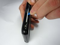
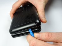
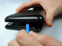
Use the iFixit Plastic Opening Tool to separate the front cover and the rear cover on all four sides.
-
-
-
-
Remove the two 0.5 cm screws using the T4 Torx screwdriver attaching the motherboard to rear cover of the GPS unit.
-
-
-
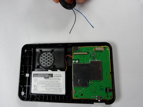
Unplug the battery from the motherboard.
-
-
-
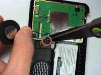
Use a pair of wire cutters to cut and separate the black speaker wire from the motherboard.
-
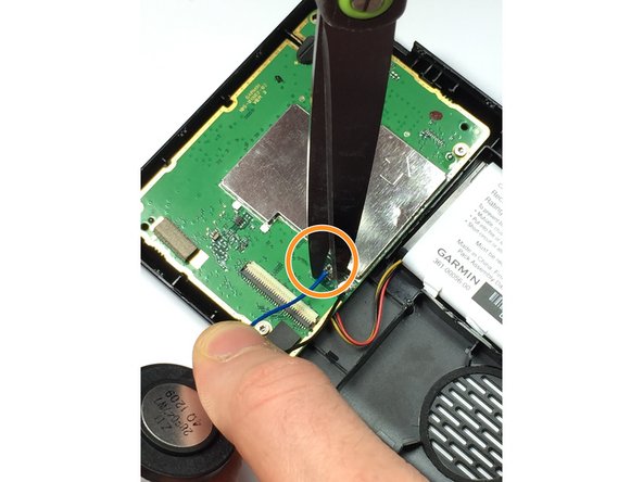
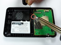
Use a pair of wire cutters to cut and separate the blue speaker wire from the motherboard.
-
-
-
Use your fingers to remove the motherboard from the rear case of the system.
-
-
-
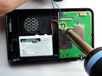
Place the replacement motherboard in the navigation system, and solder the speaker cables on the replacement motherboard.
-
Solder the black wire to the motherboard.
-
Solder the blue wire to the motherboard.
-


To reassemble your device, follow these instructions in reverse order with the exception of cutting the blue and black speaker wires.
crwdns2935221:0crwdne2935221:0
crwdns2935229:02crwdne2935229:0
crwdns2935287:0crwdne2935287:0

Sam Houston State, Team 2-7, Blackburne Fall 2015 crwdns2935289:0Sam Houston State, Team 2-7, Blackburne Fall 2015crwdne2935289:0
SHSU-BLACKBURNE-F15S2G7
crwdns2931471:04crwdne2931471:0
crwdns2935297:05crwdne2935297:0
crwdns2947412:04crwdne2947412:0
It's not a "Charging Port Replacement", it's a whole motherboard replacement, described in this guide. That's not what I'm looking for, and it's not what the guide's headline suggests.
Yes, you are right!
I was hoping it will go into SMD soldering/desoldering (using hot air, etc). Where would you find a new “motherboard”, anyways? At that point it becomes difficult to see the value in “fixing” the device.
BE VERY CAREFUL WHEN OPENING YOUR GARMIN - IT IS EXCEPTIONALLY EASY TO “TEAR” THE YELLOW FLEXIBLE CONNECTOR IF YOU ARE NOT AWARE OF THIS CONNECTOR -THEN THE GARMIN IS SCRAP - I find that the charge socket is the weakest point on these units & before I opened my last unit I threw a few out because the charge port had been damaged. The USB type C charge port can be replaced with a spare bought from an electronics part supplier, I found that I reinforced the port onto the board by soldering resistor leads to the USB socket casing & then soldered the other side onto the board to support also adding a some of glue from my glue gun. Seems that this modification increases the durability & lifespan of the unit. I also think that if the port gets damaged again I might try do a modification on the port & try solder the charger cable directly onto the board but be warned, because of the traffic antenna built into the cable I have no idea what effect this may have on the traffic function, possibly worth a try.