crwdns2915892:0crwdne2915892:0
This guide involves further disassembly of the clock radio and will require using several different tools and techniques, including using a soldering iron. If you need help on how to use a soldering iron, consult this iFixit guide: How To Solder and Desolder Connections
crwdns2942213:0crwdne2942213:0
-
-
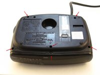
Find the battery compartment on the bottom of the clock radio.
-
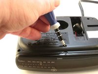
Using your thumb, push the compartment cover latch toward the battery.
-
With the latch pushed in, pull the compartment cover upward to remove it..
-
-
-
Lift the battery from the compartment.
-
Pull the battery up and gently disconnect it from the battery connector.
-
-
-
Using a Phillips #00 Screwdriver, unscrew the six 12mm screws from around the bottom of the clock radio.
-
-
-
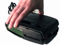
Gently pull the liquid crystal display (LCD) cover off.
-
-
-
-
Lift the top off. Two gray, plastic internal pieces will fall out when you do this; set them aside.
-
-
-
Using the wire cutters, carefully cut the plastic wire tie.
-
-
crwdns2935267:0crwdne2935267:0Tweezers$4.99
-
Follow the wires to find where they connect to the printed circuit board (PCB). At the area of connect, two spots will be marked "DC+ and "DC-."
-
Apply the rubbing alcohol to the cotton swab end. Rub the end on the hot melt glue and wait for 30 seconds, then apply the alcohol to the hot melt glue again.
-
Use the tweezers to grab the softened hot melt glue. Pull the hot melt glue off of the clock radio.
-
-
-
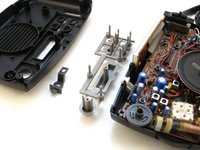
Grip the speaker.
-
Lift the speaker from the holder.
-
-
-
Locate the two 6mm screws on the PCB.
-
Using a Phillips #0 Screwdriver, unscrew the two 6 mm screws from the PCB.
-
-
-
Raise the PCB.
-
With a ruler, measure 1.8 inches from the edge of the PCB. This solder is for the DC- battery wire connection.
-
Using a ruler, measure 9 mm from the edge of the PCB. This solder is for the DC+ battery wire connection.
-
-
-
Apply the tip of the heated soldering iron to the DC- solder.
-
Pull the wire from the backside of the PCB DC-.
-
Apply the tip of the heated soldering iron to the DC+ solder.
-
Pull the wire from the backside of the PCB DC+.
-


To reassemble your device, follow these instructions in reverse order.
To reassemble your device, follow these instructions in reverse order.
crwdns2935221:0crwdne2935221:0
crwdns2935227:0crwdne2935227:0
crwdns2947410:01crwdne2947410:0
fuse resistence for mains supply for SL427 FM Radio and the same fuse resistence gets demaged frequently .....why?