crwdns2933423:0crwdne2933423:0

GE 7-4836B Alarm Clock AM-FM Radio AM-FM Switch Replacement

crwdns2942213:0crwdne2942213:0

  1. GE 7-4836B Alarm Clock AM-FM Radio AM-FM Switch Replacement, Battery Compartment Cover: crwdns2935265:01crwdnd2935265:01crwdnd2935265:03crwdne2935265:0 GE 7-4836B Alarm Clock AM-FM Radio AM-FM Switch Replacement, Battery Compartment Cover: crwdns2935265:01crwdnd2935265:02crwdnd2935265:03crwdne2935265:0 GE 7-4836B Alarm Clock AM-FM Radio AM-FM Switch Replacement, Battery Compartment Cover: crwdns2935265:01crwdnd2935265:03crwdnd2935265:03crwdne2935265:0
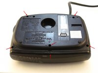
    • Find the battery compartment on the bottom of the clock radio.

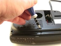
    • Using your thumb, push the compartment cover latch toward the battery.

    • With the latch pushed in, pull the compartment cover upward to remove it..

  2. GE 7-4836B Alarm Clock AM-FM Radio AM-FM Switch Replacement, Battery: crwdns2935265:02crwdnd2935265:01crwdnd2935265:02crwdne2935265:0 GE 7-4836B Alarm Clock AM-FM Radio AM-FM Switch Replacement, Battery: crwdns2935265:02crwdnd2935265:02crwdnd2935265:02crwdne2935265:0
    • Lift the battery from the compartment.

    • Pull the battery up and gently disconnect it from the battery connector.

  3. GE 7-4836B Alarm Clock AM-FM Radio AM-FM Switch Replacement, Screws: crwdns2935265:03crwdnd2935265:01crwdnd2935265:02crwdne2935265:0 GE 7-4836B Alarm Clock AM-FM Radio AM-FM Switch Replacement, Screws: crwdns2935265:03crwdnd2935265:02crwdnd2935265:02crwdne2935265:0
    • Using a Phillips #00 Screwdriver, unscrew the six 12mm screws from around the bottom of the clock radio.

  4. GE 7-4836B Alarm Clock AM-FM Radio AM-FM Switch Replacement, LCD Cover: crwdns2935265:04crwdnd2935265:01crwdnd2935265:01crwdne2935265:0
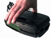
    • Gently pull the liquid crystal display (LCD) cover off.

  5. GE 7-4836B Alarm Clock AM-FM Radio AM-FM Switch Replacement, Clock Radio: crwdns2935265:05crwdnd2935265:01crwdnd2935265:02crwdne2935265:0 GE 7-4836B Alarm Clock AM-FM Radio AM-FM Switch Replacement, Clock Radio: crwdns2935265:05crwdnd2935265:02crwdnd2935265:02crwdne2935265:0
    • Lift the top off. Two gray, plastic internal pieces will fall out when you do this; set them aside.

  6. GE 7-4836B Alarm Clock AM-FM Radio AM-FM Switch Replacement, Battery Wires Wire Tie: crwdns2935265:06crwdnd2935265:01crwdnd2935265:02crwdne2935265:0 GE 7-4836B Alarm Clock AM-FM Radio AM-FM Switch Replacement, Battery Wires Wire Tie: crwdns2935265:06crwdnd2935265:02crwdnd2935265:02crwdne2935265:0
    • Using the wire cutters, carefully cut the plastic wire tie.
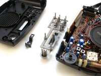
  7. GE 7-4836B Alarm Clock AM-FM Radio AM-FM Switch Replacement, Speaker: crwdns2935265:07crwdnd2935265:01crwdnd2935265:01crwdne2935265:0
    • Grip the speaker.

    • Lift the speaker from the holder.

  8. GE 7-4836B Alarm Clock AM-FM Radio AM-FM Switch Replacement, Screws: crwdns2935265:08crwdnd2935265:01crwdnd2935265:02crwdne2935265:0 GE 7-4836B Alarm Clock AM-FM Radio AM-FM Switch Replacement, Screws: crwdns2935265:08crwdnd2935265:02crwdnd2935265:02crwdne2935265:0
    • Locate the two 6mm screws on the PCB.

    • Using a Phillips #0 Screwdriver, unscrew the two 6 mm screws from the PCB.

  9. GE 7-4836B Alarm Clock AM-FM Radio AM-FM Switch Replacement, AM-FM Switch Dial Screw: crwdns2935265:09crwdnd2935265:01crwdnd2935265:02crwdne2935265:0 GE 7-4836B Alarm Clock AM-FM Radio AM-FM Switch Replacement, AM-FM Switch Dial Screw: crwdns2935265:09crwdnd2935265:02crwdnd2935265:02crwdne2935265:0
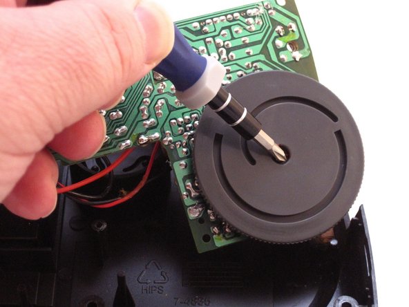
    • Raise the PCB to expose the AM-FM switch dial screw.

    • Using a Phillip's #01 Screwdriver, unscrew the one 3mm screw from the middle of the AM-FM switch dial.

  10. GE 7-4836B Alarm Clock AM-FM Radio AM-FM Switch Replacement, AM-FM Pins: crwdns2935265:010crwdnd2935265:01crwdnd2935265:03crwdne2935265:0 GE 7-4836B Alarm Clock AM-FM Radio AM-FM Switch Replacement, AM-FM Pins: crwdns2935265:010crwdnd2935265:02crwdnd2935265:03crwdne2935265:0 GE 7-4836B Alarm Clock AM-FM Radio AM-FM Switch Replacement, AM-FM Pins: crwdns2935265:010crwdnd2935265:03crwdnd2935265:03crwdne2935265:0
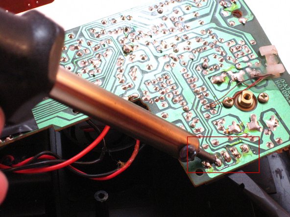
    • Locate the AM-FM pins on the PCB.

    • Carefully apply the hot soldering iron to the solder on top of the AM-FM pins.

    • Gently and firmly push on the pins with the Spudger to remove the switch from the underside of the PCB.

crwdns2915888:0crwdne2915888:0

To reassemble your device, follow these instructions in reverse order.

Dominick Giguere

crwdns2935283:010/28/14crwdne2935283:0

848 crwdns2915208:0crwdne2915208:0

crwdns2935297:06crwdne2935297:0

crwdns2944067:00crwdne2944067:0

crwdns2917038:0crwdne2917038:0

crwdns2936625:0crwdne2936625:0:

crwdns2936751:024crwdne2936751:0 0

crwdns2936753:07crwdne2936753:0 0

crwdns2936753:030crwdne2936753:0 17

crwdns2942667:0crwdne2942667:0 1,072