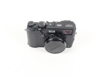
crwdns2915892:0crwdne2915892:0
Follow these steps to replace the motherboard. The motherboard should only be replaced after other troubleshooting steps have been attempted.
crwdns2942213:0crwdne2942213:0
-
-
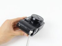
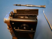
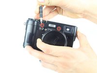
Slide the small black tab on the bottom of the camera to the left to unlock the battery cover.
-
-
-
Push the orange tab up to release the battery.
-
Slide the battery out of the camera.
-
-
-
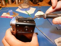
Beginning in one of the corners, use a spudger to pry the leather casing off of the camera.
-
-
-
Carefully and slowly peel the leatherette skin off of the camera by hand.
-
-
-
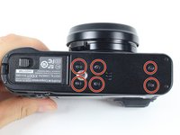
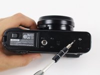
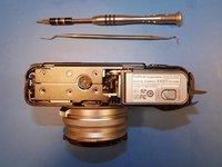
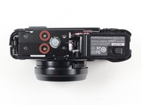
Locate the six 4.0 mm screws on the bottom of the camera.
-
Use a JIS#000 driver to remove these screws.
-
-
crwdns2935267:0crwdne2935267:0Mako Driver Kit - 64 Precision Bits$39.95
-
This is a camera produced by a Japanese camera manufacturer. The Japanese camera industry loves using JIS (Japanese Industrial Standard) screws.
-
Don't be tempted by your Phillips screw driver collection. Although PH#00 will interchange with JIS#00, it is not a perfect fit. Using Phillips will cause more wear on the head of the JIS screws and cause the screws to prematurely strip.
-
Have both JIS#00 and JIS#000 screw drivers available for this teardown. Luckily, both bits are included in the ifixit 64bit kit.
-
-
-
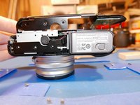
Remove the bottom plate and the tripod mount by lifting them using your hands.
-
The tripod mount is keyed and fits into a series of pegs on the back side of the bottom plate.
-
-
-
Get your picks ready!
-
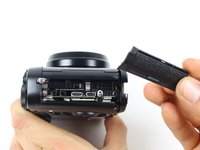
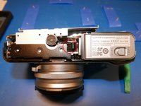
To get any deeper into this camera, the right-hand port cover assembly must be removed first. Once this is removed, you will have access to the screws that secure the other components.
-
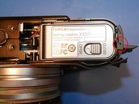
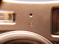
There's a tiny hole toward the bottom right of the battery compartment. Using the pick tool, press into that hole.
-
A plastic rod will release. That plastic rod is the axis the hinge rotates about.
-
-
-
Fuji! What did we tell you about hiding screws behind closed doors! That's pretty under the table Fuji. Don't do it again. Promise?
-
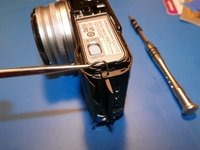
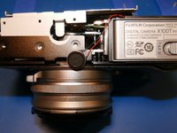
The devil's in the details with this camera. Slide the port cover off the hinge rod.
-
Using a pair of pliers, pull the rod out of the top plate of the camera. Now you'll finally have access to all the screws that need to be removed.
-
-
-
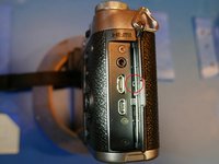
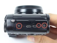
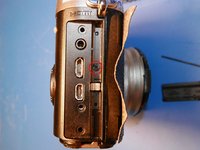
Remove the three 5.0 mm screws by the micro-USB, micro-HDMI and remote ports.
-
Remove the screw hidden behind the port cover hinge.
-
The port cover assembly should come off with ease. If it is stuck, try prying with plastic shims.
-
-
-
Remove the two 6.0 mm screws beneath the port cover assembly.
-
-
-
Remove the four 5.0 mm screws on the side of the camera that is opposite to the battery.
-
-
-
Remove the two 2.5 mm screws on the bottom face of the camera.
-
-
-
Once the electronics are exposed, it is highly recommended that you remain ESD safe. ESD can fry your precious electronics, and pass thousands of volts through components only rated for a few V DC. ESD can sure ruin your day if you are not careful.
-
Use an ESD mat and wrist strap, and make sure you are grounded for the remaining of the teardown. Make sure your ESD mat is connected to the ground of a nearby outlet, and make sure your house actually has a ground. Consult an electrician if you are unsure.
-
-
-
-
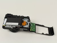
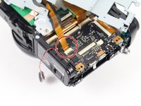
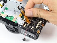
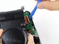
Remove the orange ribbon cable by opening up the ZIF connector with a plastic prying tool or toothpick.
-
-
-
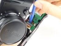
Remove the white/blue ribbon cable from the motherboard by gently pulling with your hands.
-
-
-
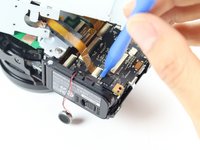
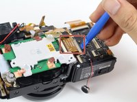
Remove the 2.5 mm screw in the center, above the removed LCD screen.
-
Remove the two 4.0 mm screws on the right.
-
-
-
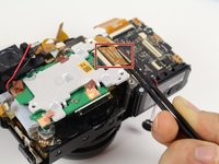
Remove the two 4.5 mm screws on the side of the camera opposite of the battery.
-
-
-
Peel off the copper tape connecting the frame to the camera.
-
-
-
Remove the adhesive tape holding the speaker.
-
The speaker is held into place by double sided tape. Pull it off the steel frame and move it toward the bottom of the camera
-
-
crwdns2935267:0crwdne2935267:0Tweezers$4.99
-
Remove these two ribbon cables so they don't get cut or damaged when removing the entire steel frame.
-
-
-
Fold back the steel frame by lifting it off and gently pulling it to the side using your hand.
-
Remove the three 4.2 mm screws on the green chip.
-
-
-
Locate the orange ribbon cable on the side of the camera that has the battery slot.
-
Remove the ribbon cable from the ZIF socket using a plastic opening tool.
-
Remove the ribbon by lifting it off with your hands.
-
-
-
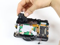
Remove the rubber eyepiece guard by lifting it off with your hands.
-
If the rubber eyepiece is being stubborn, an old giftcard won't mind :D
-
-
-
Remove the two 4.0 mm screws from the front of the camera. These are most likely T1 torx screws.
-
I can't stress enough how tiny these screws are. Pencil point sized.
-
The closest bit in the ifixit kit is the star shaped #2 screw head.
-
-
-
Remove the top frame by lifting it off and pulling it towards the backside of the camera.
-
-
-
Use a plastic opening tool to detach the two ribbon cables from the top frame.
-
-
-
Locate the adhesive connecting the black and red wires above the green board.
-
Remove the adhesive by gently pulling it off with your hand.
-
Remove the copper tape that grounds the sensor heatsink to the sensor PCB.
-
-
-
Use a plastic opening tool to pry off the ribbon located next to the top-right of the green sensor board.
-
-
-
Use a plastic opening tool and metal tweezers to lift up the ribbon located next to the center-right section of the green board.
-
Remove the CMOS sensor aluminum heatsink by lifting it up with your hands. The sensor, PCB and heatsink are integrated into one unit.
-
-
-
You should be wearing nitrile gloves when working with lens assemblies. Oils from fingerprints leave marks on the lens elements and cause major headaches during reassembly.
-
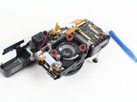
Remove the four 3.2 mm screws on the silver lens cover.
-
-
-
Use a plastic opening tool to lift up the silver lens cover.
-
-
-
Remove the three 3.5 mm screws on the black lens cover.
-
-
-
Lift up the black lens cover with your hands.
-
-
-
Remove the three 3.5 mm screws on the spring-loaded cover.
-
-
-
Remove the spring and the lens by gently lifting both the components upwards.
-
-
-
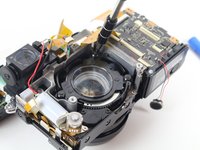
Once the lens has been taken off, flip the camera over and unscrew the two 4.0 mm screws on the front of the camera, next to the lens cover.
-
-
-
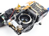
Remove the two 4.0 mm screws located on the side of the camera.
-
-
crwdns2935267:0crwdne2935267:0Tweezers$4.99
-
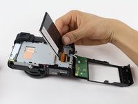
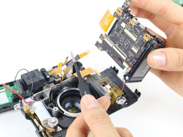
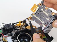
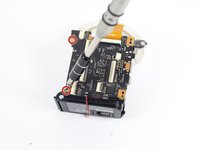
Slowly pull the now unscrewed motherboard off of the camera
-
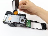
Using the metal tweezers, pull apart the orange ribbon from the motherboard.
-
-
-
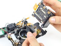
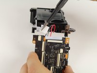
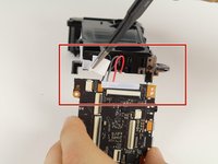
Using the precision tweezers, remove the white strip from the corner of the motherboard.
-
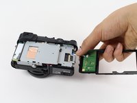
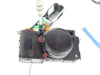
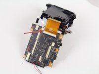
Remove the two 4.0 mm screws from the top left and the bottom left.
-
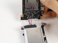
After the screws are removed, carefully detach the motherboard from the battery case by carefully separating the two parts.
-
-
-
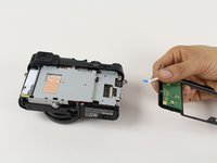
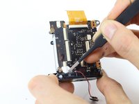
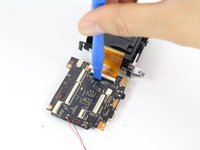
Use the plastic opening tool to remove the orange ribbon on the motherboard by wedging the tool under the ribbons black tab, and carefully prying upwards.
-
-
-
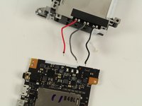
Desolder the wires connecting the motherboard and battery case.
-


To reassemble your device, follow these instructions in reverse order.
To reassemble your device, follow these instructions in reverse order.
crwdns2935221:0crwdne2935221:0
crwdns2935229:02crwdne2935229:0
crwdns2915084:0crwdne2915084:0

Cal Poly, Team 70-1, Forte Winter 2016 crwdns2935289:0Cal Poly, Team 70-1, Forte Winter 2016crwdne2935289:0
CPSU-FORTE-W16S70G1
crwdns2931471:04crwdne2931471:0
crwdns2935297:09crwdne2935297:0
crwdns2947412:02crwdne2947412:0
Thank you for this. Such a valuable resource. Where can i get a replacement motherboard for this camera
This was a great guide for me to dissemble my Fuji X100S, to remove the Motherboard and replace F401 fuse. I was able to follow your clear instructions, particularly with all of the photos. Thank you very much.