crwdns2915892:0crwdne2915892:0
If the buttons on your Fujifilm FinePix T500 camera are unresponsive, the issue may be with the circuit board. Replacing the circuit board can restore functionality, but it requires careful handling of small components. Be cautious when working with internal electronics, as improper handling can cause further issues. Follow this step-by-step guide to safely complete the repair.
crwdns2942213:0crwdne2942213:0
-
-
Unscrew the six 3.5mm Philips head from the outer casing.
-
-
-
Open the battery compartment and remove the battery.
-
Carefully pry the front half of the casing away from the camera.
-
Pay close attention to the sensor cover—a small piece of translucent plastic—as it may fall out of place. If it does, place it back in its original position.
-
-
-
Pry the back half of the casing from the camera.
-
-
-
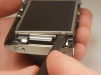
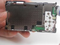
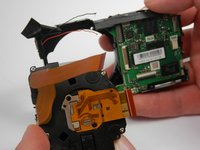
Lift the LCD screen out of the camera.
-
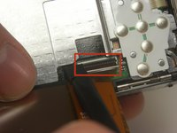
Locate the tab securing the ribbon cable that connects the screen to the motherboard. Using a spudger, gently lift the tab to release the ribbon. Carefully disconnect the screen from the motherboard.
-
-
-
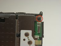
Unscrew the 3.5 mm Phillips head screw from the corner of the camera.
-
-
-
Pry off the center casing of the camera. Separate the top and side sections individually before fully removing the casing.
-
-
-
-
Unscrew the two 3.5 mm Phillips head screws in the metal plate.
-
-
-
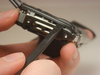
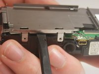
Pry the metal plate out using the spudger.
-
-
-
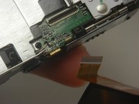
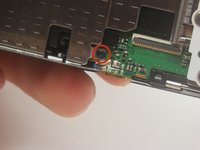
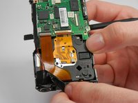
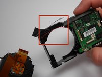
Peel back the strip of black tape to reveal a red and black wire.
-
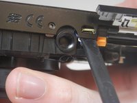
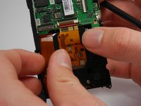
Detach the orange ribbon by gently pulling on it.
-
Detach the golden ribbon by gently lifting it with the spudger.
-
-
-
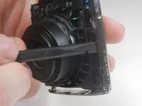
The lens should now be free to simply be pushed out of its socket.
-
The black and red wires that were exposed previously may be in the way of removing the lens and may break. If they do, you will need to solder these wires back into place upon reassembly.
-
-
crwdns2935267:0crwdne2935267:0Tweezers$4.99
-
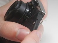
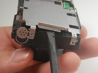
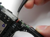
Use tweezers to pull back the plastic covering the top of the camera.
-
-
-
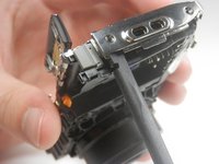
Use tweezers to disconnect both the red and the black wires located next to the flash of the camera.
-
-
-
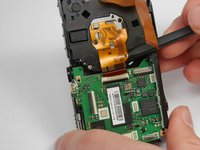
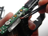
Pry off the top circuit board using the spudger.
-
-
-
Use tweezers to disconnect the blue and white wires on the underside of the camera.
-
-
-
Push the motherboard out of the camera body.
-
-
-
Desolder the red, black, and white wires from the circuit board that you pried off earlier.
-


To reassemble your device, follow these instructions in reverse order.
crwdns2935221:0crwdne2935221:0
crwdns2935229:02crwdne2935229:0
crwdns2935287:0crwdne2935287:0

USF Tampa, Team 19-3, Blackwell Winter 2015 crwdns2935289:0USF Tampa, Team 19-3, Blackwell Winter 2015crwdne2935289:0
USFT-BLACKWELL-W15S19G3
crwdns2931471:04crwdne2931471:0
crwdns2935297:010crwdne2935297:0