crwdns2915892:0crwdne2915892:0
How to remove and replace the logic board.
crwdns2942213:0crwdne2942213:0
-
-
Slide the battery cover to the side to release the batteries.
-
-
-
Remove the five screws from the camera casing using a tri-point Y0 screwdriver.
-
-
-
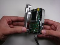
Grab the case with your hands and slowly pull back the outer casing.
-
-
-
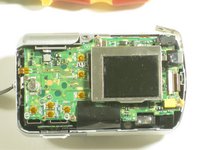
Locate the LCD screen and anchoring screw.
-
Remove screw.
-
-
-
-
Carefully pull the LCD screen away from the board it is connected to.
-
-
-
Push both blue switches away from the holding device to detach the LCD ribbon.
-
-
-
Carefully detach the ribbon from where it was connected by the blue pins.
-
-
-
Now that everything has been disconnected from the board, remove LCD screen.
-
-
-
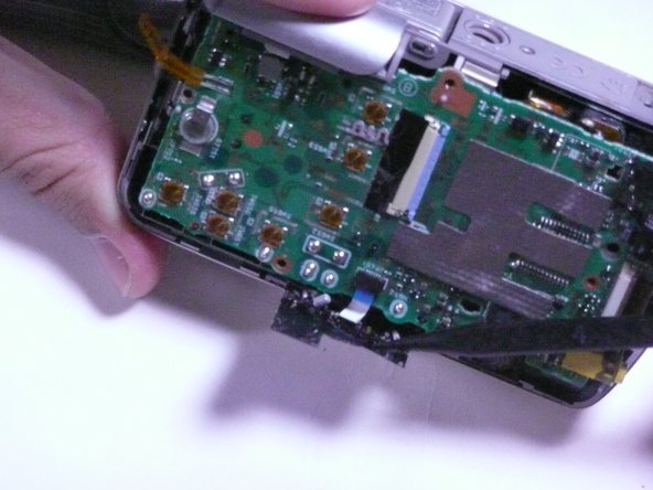
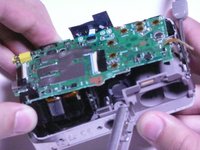
Remove the two screws holding the circuit board down.
-
-
-
Remove the black sticky tape from the circuit board and camera case.
-
-
-
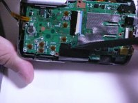
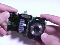
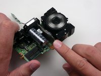
Gently pull the circuit board away from the front side of the camera.
-
-
-
Remove the motherboard by pulling it straight away from the assembly.
-


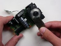
To reassemble your device, follow these instructions in reverse order.
crwdns2935287:0crwdne2935287:0

Cal Poly, Team 7-11, Maness Spring 2010 crwdns2935289:0Cal Poly, Team 7-11, Maness Spring 2010crwdne2935289:0
CPSU-MANESS-S10S7G11
crwdns2931471:03crwdne2931471:0
crwdns2935297:04crwdne2935297:0