crwdns2915892:0crwdne2915892:0
This guide explains how to replace the flash unit of a FujiFilm FinePix A340 camera.
The flash unit is a mechanism within a camera that creates a "flash" or quick burst of light while a photo is taken to illuminate the image. If the "flash" function of your camera is not working, you may need to replace your flash unit.
Note that this guide involves soldering, or using a special tool called a soldering iron to delicately weld parts together.
crwdns2942213:0crwdne2942213:0
-
-
Slide the battery cover to the side to release the batteries.
-
-
-
Remove the five screws from the camera casing using a tri-point Y0 screwdriver.
-
-
-
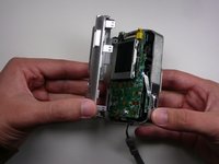
Grab the case with your hands and slowly pull back the outer casing.
-
-
-
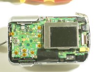
Locate the LCD screen and anchoring screw.
-
Remove screw.
-
-
-
Carefully pull the LCD screen away from the board it is connected to.
-
-
-
-
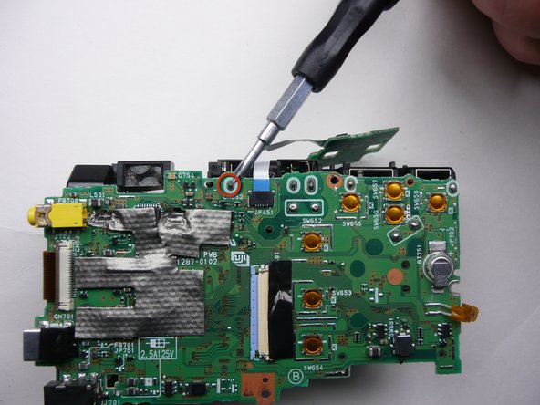
Push both blue switches away from the holding device to detach the LCD ribbon.
-
-
-
Carefully detach the ribbon from where it was connected by the blue pins.
-
-
-
Now that everything has been disconnected from the board, remove LCD screen.
-
-
-
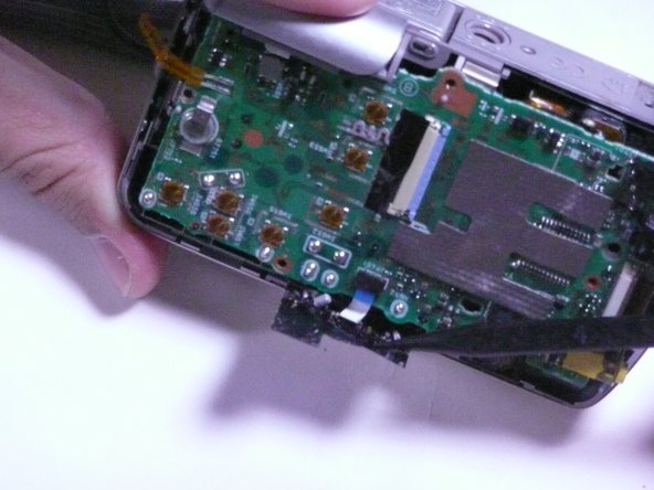
Remove the two screws holding the circuit board down.
-
-
-
Remove the black sticky tape from the circuit board and camera case.
-
-
-
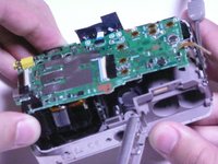
Gently pull the circuit board away from the front side of the camera.
-
-
-
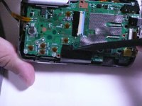
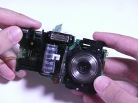
Remove the motherboard by pulling it straight away from the assembly.
-
-
-
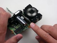
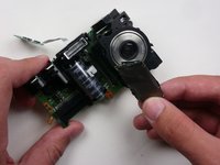
Locate the flash unit of the camera. It includes the camera's flash and a capacitor.
-
-
-
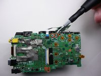
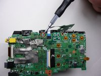
Desolder the flash unit at its three points.
-
Learn more about electronics soldering here.
-


To reassemble your device, follow these instructions in reverse order.
crwdns2935221:0crwdne2935221:0
crwdns2935227:0crwdne2935227:0
crwdns2935287:0crwdne2935287:0

Cal Poly, Team 7-11, Maness Spring 2010 crwdns2935289:0Cal Poly, Team 7-11, Maness Spring 2010crwdne2935289:0
CPSU-MANESS-S10S7G11
crwdns2931471:03crwdne2931471:0
crwdns2935297:04crwdne2935297:0