crwdns2915892:0crwdne2915892:0
Mainboard removal prereq guide
crwdns2942213:0crwdne2942213:0
-
-
Before you begin repairs, unplug your laptop and shut it down from the operating system. This ensures that the laptop isn't in standby/suspend mode.
-
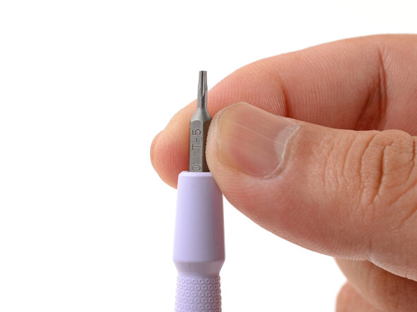
Make sure your Framework Screwdriver has the T5 Torx bit (labeled as T-5) facing outwards. If it's not, pull the bit out and flip it.
-
-
-
Set your Framework Laptop face-down on a clean work surface.
-
-
-
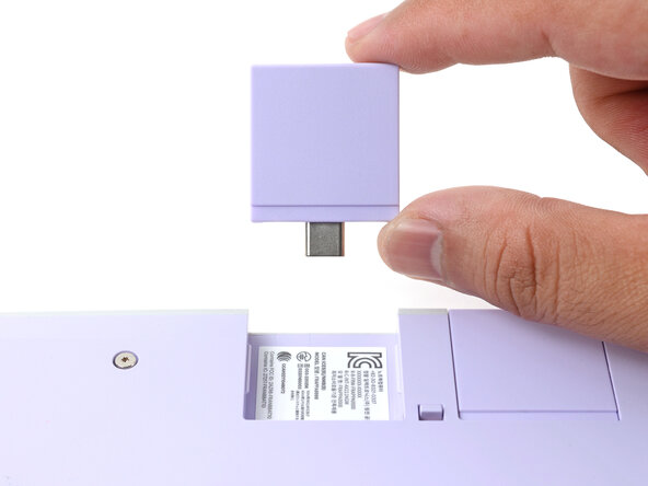
Use your fingers to flip the two Expansion Card latches (one for each side) into the unlocked position.
-
-
-
Grip the lip of an Expansion Card with your fingers.
-
Pull the Expansion Card out of its slot and remove it.
-
Repeat this procedure to remove all remaining Expansion Cards.
-
-
-
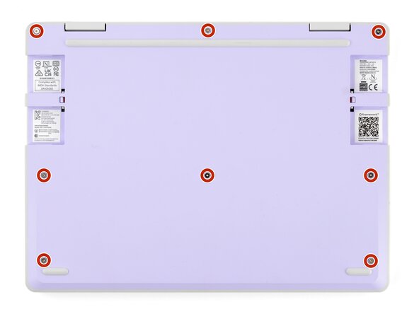
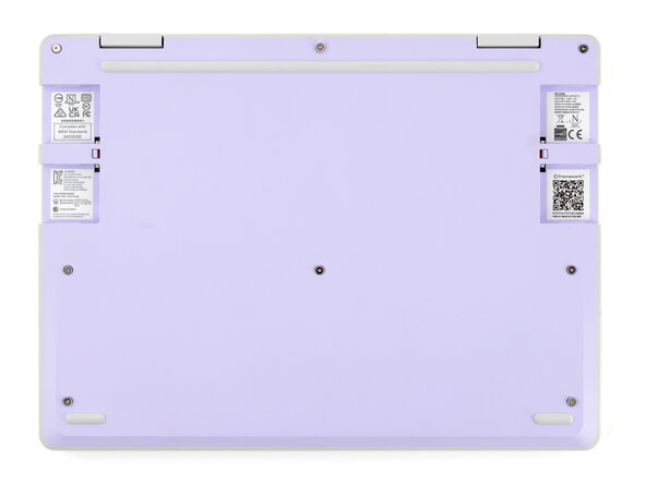
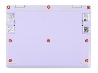
Use your Framework Screwdriver to fully loosen the eight captive T5 Torx screws on the bottom of your laptop.
-
-
-
Flip your laptop face-up on your work surface.
-
-
-
Open the laptop lid so that both the screen and the base lie flat on your work surface.
-
-
-
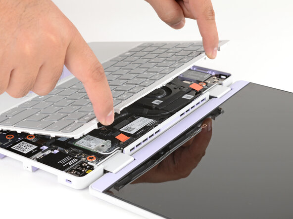
Use your fingers to grip the Input Cover in the hinge cutouts.
-
Lift upwards to swing the Input Cover up from the base of the laptop.
-
Remove the Input Cover.
-
-
-
Use your Framework Screwdriver to loosen the six captive T5 Torx screws securing the battery.
-
-
-
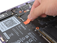
Grab the orange battery tab with your fingers and lift straight up to disconnect the battery.
-
-
-
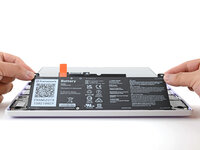
Lift and remove the battery from the laptop.
-
-
-
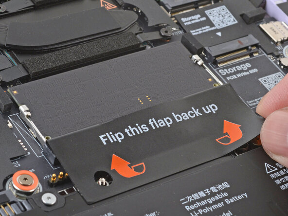
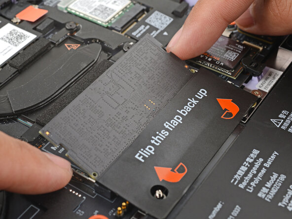
Use your fingers to flip open the memory flap.
-
-
-
Use your fingers to spread the clips on both sides of the memory module apart to unclip the memory.
-
-
-
-
Use your fingers to grab the memory module by its edges.
-
Slide the memory module out of its socket and remove it.
-
-
-
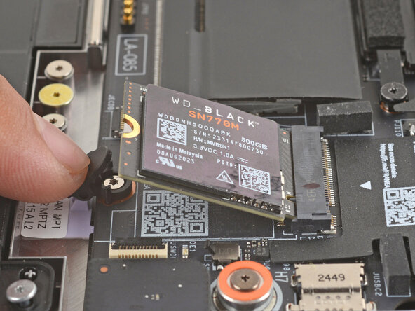
Use your finger to press down on the black SSD latch to unlatch the SSD.
-
-
-
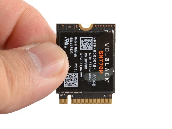
Grab the SSD by its edges and pull it out of its socket.
-
Remove the SSD.
-
-
-
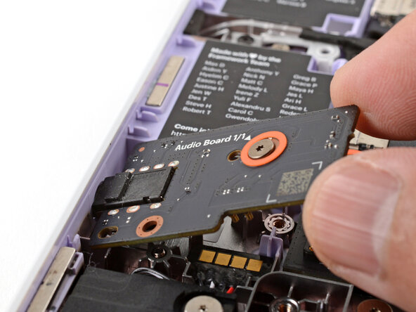
Use your Framework Screwdriver to loosen the captive T5 Torx screw securing the Audio Board along the left edge of the laptop.
-
-
-
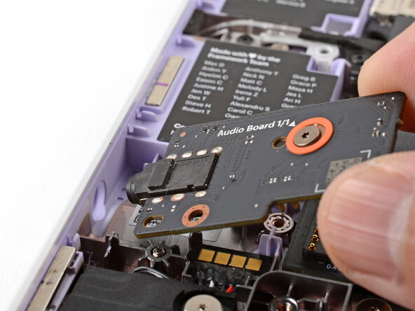
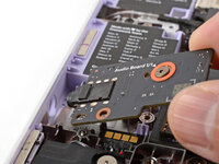
Use your fingers to lift the right edge of the Audio Board and pull it out of its recess.
-
Remove the Audio Board.
-
-
-
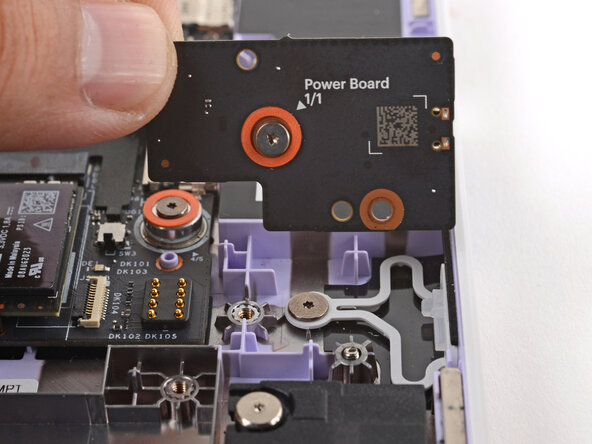
Use your Framework Screwdriver to loosen the captive T5 Torx screw securing the Power Button Board (labeled "Power Board").
-
-
-
Use your fingers to lift and remove the Power Button Board.
-
-
-
Use your Framework Screwdriver to loosen the captive T5 Torx screw securing the Wi-Fi card bracket.
-
-
-
Grab the Wi-Fi card bracket with your fingers and slide it off the top of the Wi-Fi card.
-
Remove the bracket and store it in a safe location for reassembly.
-
-
-
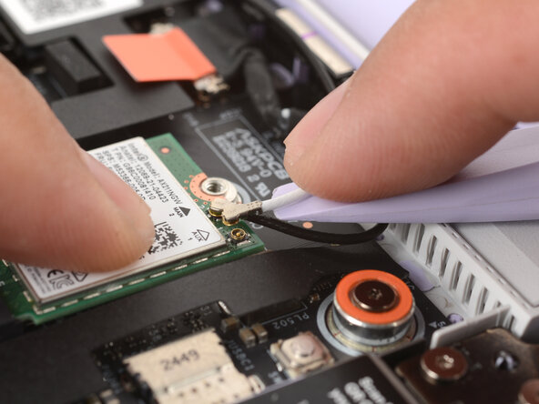
Press and hold the Wi-Fi card down with your finger.
-
Slide the flat edge of your Framework Screwdriver under the white antenna cable, as close to the metal head as possible.
-
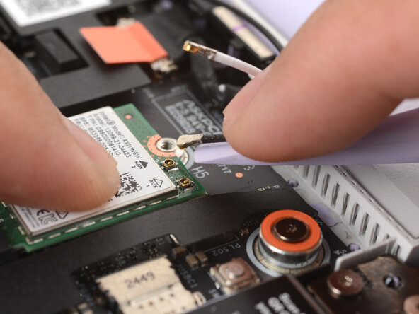
Gently lift the connector straight up to disconnect the white antenna cable.
-
Repeat the procedure with the black antenna cable.
-
-
-
Grab the Wi-Fi card by the edges and pull it out of its socket.
-
Remove the Wi-Fi card.
-
-
-
Use the flat end of your Framework Screwdriver to gently push on one of the fan connector's protruding edges, then the other, to loosen the connector out of its socket.
-
-
-
Use your fingers and your Framework Screwdriver to slide the fan connector out of its socket.
-
-
-
Use your Framework Screwdriver to loosen the two captive T5 Torx screws securing the fan.
-
-
-
Lift and remove the fan.
-
-
-
Use your Framework Screwdriver to loosen the four captive T5 Torx screws securing the heatsink.
-
-
-
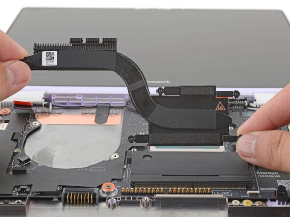
Slide the flat end of your Framework Screwdriver under the heatsink arm labeled "2".
-
Gently twist the Framework Screwdriver to lift the heatsink arm and loosen the heatsink.
-
Repeat the procedure with the heatsink arm labeled "3".
-
-
-
Lift and remove the heatsink.
-
-
-
Use your Framework Screwdriver to loosen the captive T5 Torx screw securing the Wi-Fi card bracket.
-
-
-
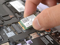
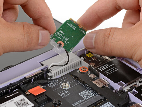
Grab the Wi-Fi card by its edges and slide it out of its socket.
-
-
-
Carefully reposition the Wi-Fi card away from the Mainboard.
-
-
-
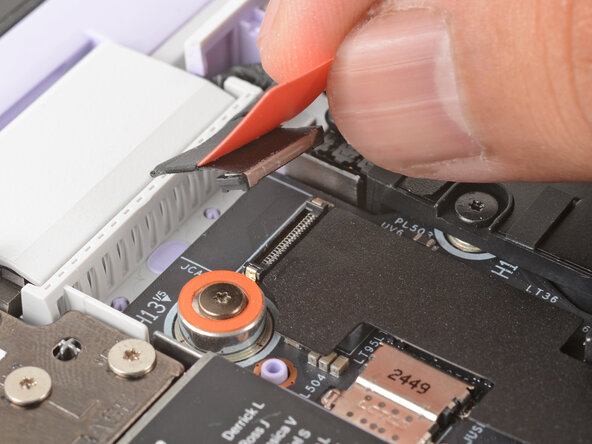
Use your fingers to grab the orange tab on the webcam cable, located near the left hinge.
-
Lift straight up to disconnect the cable.
-
-
-
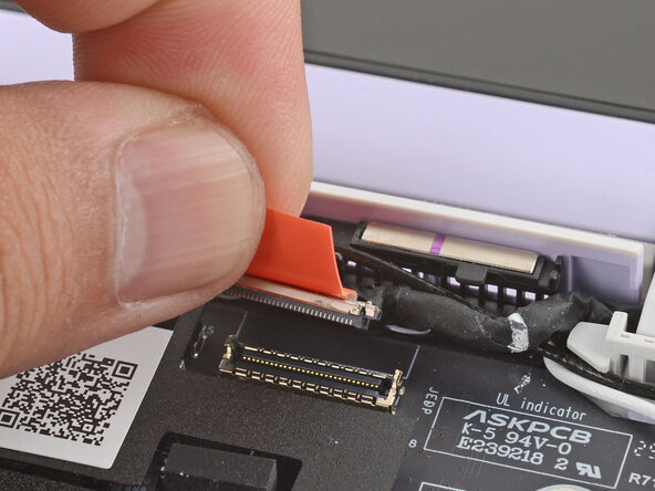
Use your fingers to grab the orange tab on the display cable, located near the right hinge.
-
Lift straight up to disconnect the cable.
-
-
-
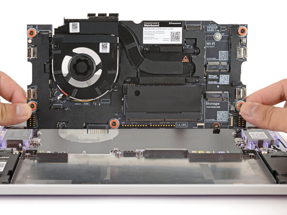
Use your Framework Screwdriver to loosen the five captive T5 Torx screws securing the Mainboard.
-
-
-
Use your fingers to grab the Mainboard by its edges.
-
Lift and remove the Mainboard.
-