crwdns2915892:0crwdne2915892:0
If your Flydigi Apex 5 does not charge, or its onboard screen is not functioning, the cause may be from an issue with the USB-C daughterboard. Replacing the daughterboard or ensuring all components are connected properly can resolve these issues.
Follow this guide to replace the Flydigi Apex 5 USB-C daughterboard, or to ensure all parts are connect properly.
crwdns2942213:0crwdne2942213:0
-
-
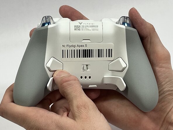
Orient the controller so that its back is facing you.
-
Apply firm downward pressure to remove both the M3 and M4 back paddles.
 crwdns2952109:0crwdne2952109:0
-
-
-
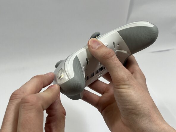
Turn the controller over so its front faces you.
-
Remove the D-pad by firmly pulling it away from the body of the controller.
-
-
-
Remove the clear, magnetically-adhered faceplate of the controller by firmly pulling it away from the body of the controller starting from the edge of the faceplate.
-
-
-
Remove the small cover from the rear of the controller by pushing it upward.
-
Remove the two 5.8mm screws behind the battery cover using a Phillips #0 screwdriver.
-
-
-
Turn the controller over so its front faces you.
-
Remove the six 10mm long screws from the front of the controller using a Torx T6 screwdriver.
-
-
-
Insert the plastic opening tool between the top and bottom plastic controller molds, then pry until the two pieces separate.
-
-
-
-
Carefully remove the back paddle ribbon cable with the angled tweezers or spudger.
-
-
-
Press a prong of each side of the angled tweezers under the lip of the power supply cable connector and pull the plastic connector out of its terminal.
-
Pull the power supply cable through the plastic cable guides.
-
-
-
Pry up the battery with the plastic hook and pry tool.
-
-
-
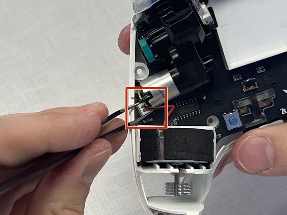
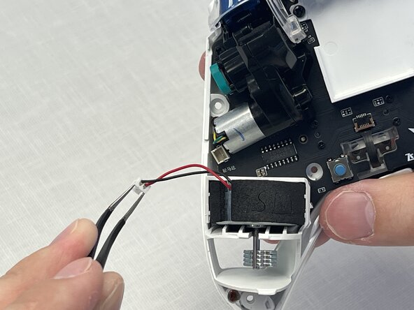
Press a prong of each side of the angled tweezers under the lip of the motor's power supply connector and pull the plastic connector out of its terminal.
-
Lift the motor directly upward out of its casing.
-
-
-
Press a prong of each side of the curved tip tweezers under the lip of the motor's power supply connector and pull the plastic connector out of its terminal.
-
Lift the motor directly upward out of its casing.
-
-
-
Remove the USB-C faceplate by inserting the spudger as shown, pushing the spudger forward while twisting slightly.
-
-
-
Remove the two 10mm screws using a Phillips #0 screwdriver.
-
Remove the plastic battery mold by lifting away from the controller.
-
-
-
Remove the four 5mm screws using a Phillips #00 screwdriver.
-
Remove the two vibration motor housings by pulling away from the controller.
-
-
-
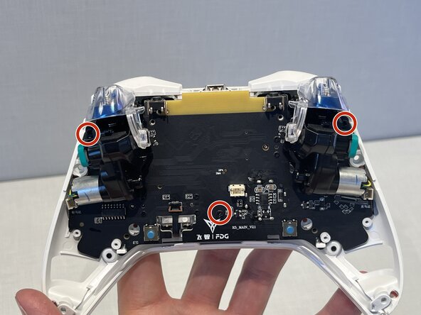
Remove the three 10mm screws using a Phillips #1 screwdriver.
-
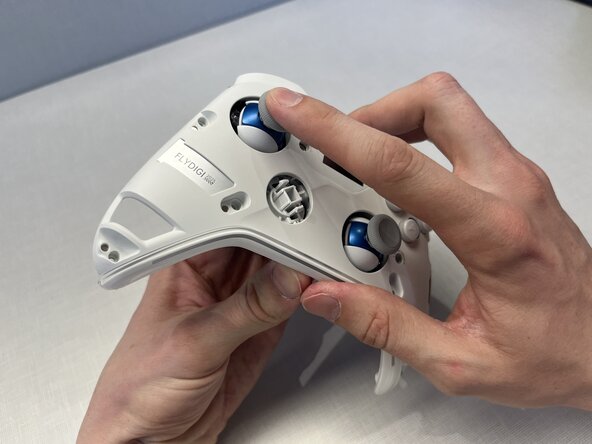
Use your index finger to push on the left joystick, while also pulling on the motherboard with your other hand.
-
-
-
Use a pair of tweezers to push against the black latch to open the ribbon connector.
-
Use the pair of tweezers to gently pull the ribbon out of its connection.
-
-
-
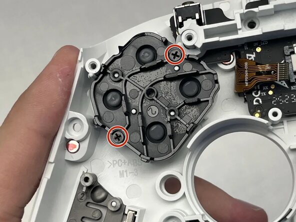
Use a Phillips #0 screwdriver to remove the two 5mm screws connecting the D-pad to the front of the controller.
-
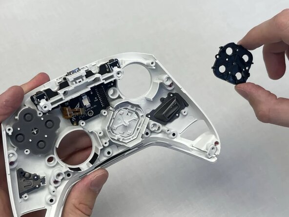
Remove the black plastic cover holding the D-pad to the front of the controller.
-
-
-
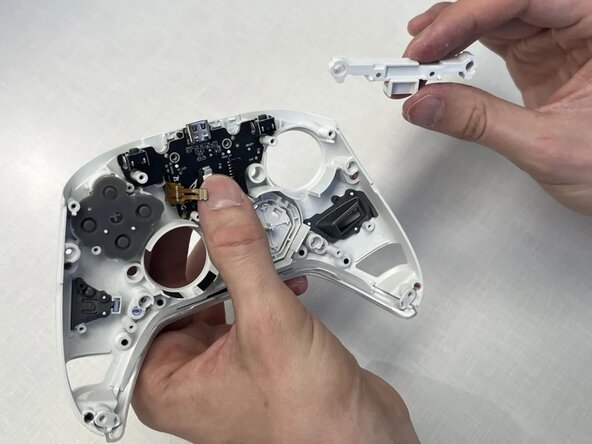
Use a Phillips #0 screwdriver to remove the two 7mm screws.
-
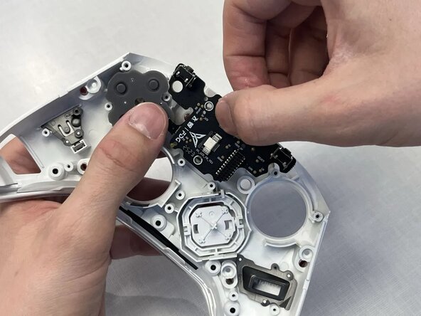
Remove the plastic bridge covering the USB-C daughterbord.
-
Pull the USB-C daughterboard away from the front of the controller.
-












To reassemble your device, follow these instructions in reverse order.

crwdns2935287:0crwdne2935287:0

Idaho State University, Team 1-3, Watkins Spring 2026 crwdns2935289:0Idaho State University, Team 1-3, Watkins Spring 2026crwdne2935289:0
ISU-WATKINS-S26S1G3
crwdns2931471:04crwdne2931471:0
crwdns2935297:05crwdne2935297:0
