crwdns2915892:0crwdne2915892:0
This guide demonstrates how to replace the paper eject frame assembly in your Epson Stylus Photo 1400 printer. If you're experiencing frequent paper jams, a faulty eject frame may be the cause. This repair requires basic tools and minimal technical experience, making it suitable for most users. Follow these steps to resolve paper jam issues and restore smooth operation.
crwdns2942213:0crwdne2942213:0
-
-
Turn off the printer.
-
Disconnect all data connections coming into the printer such as USB, networkd cables, firewire, etc. as well as removing the power cord.
-
-
-
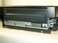
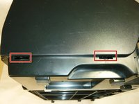
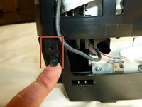
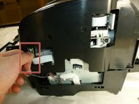
Locate the IEEE cover in the back.
-
Gently slide the cover to the right to unlatch, then pull to remove it.
-
-
-
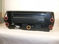
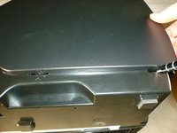
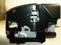
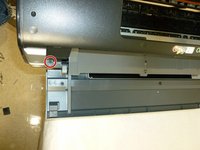
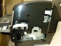
Using a Phillips #2 screwdriver, remove the four 10 mm screws shown.
-
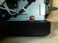
Remove the 6 mm screw that holds the rear housing in place.
-
-
-
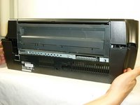
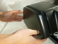
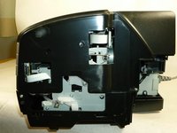
Remove the rear housing by pulling it backwards.
-
-
-
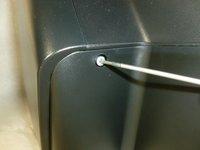
Insert a plastic opening tool into the cutouts of the lower housing.
-
Release the two tabs of the side housing by lifting the tool in an upward motion.
-
Remove the side housing by pulling it outwards.
-
-
-
Using the same method, remove the other side housing.
-
-
-
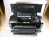
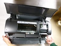
Lift the paper support.
-
Open the printer cover and front cover.
-
-
-
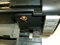
Remove the four 10 mm Phillips #2 screws from the sides of the printer.
-
Remove the three 6 mm Phillips #2 screws.
-
-
-
-
Detach the tabs from the pins on each side by pulling it outwards.
-
-
-
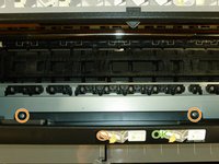
Remove the two 10 mm Phillips #2 screws on the front of the printer.
-
-
-
Disconnect the two cables on the side by carefully pulling it outwards.
-
-
-
Remove the upper housing by lifting it upwards.
-
-
-
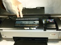
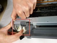
Start by emptying the ink tube.
-
Hold the left side of the ink tube in your hand.
-
Pull the sides of the tube apart and empty the waste.
-
-
-
Remove the acetate tape that secures the connector cable.
-
-
-
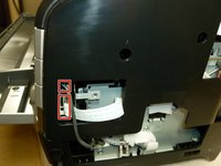
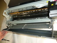
Remove the first three 10 mm screws that hold the printer mechanism in place using a Phillips #2 screwdriver.
-
-
-
Remove the other three 10 mm screws that secure the printer mechanism using a Phillips #2 screwdriver.
-
-
-
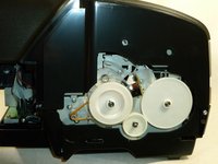
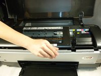
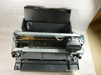
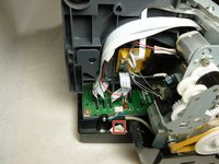
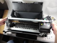
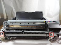
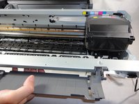
The printer mechanism is located on the lower housing.
-
Remove the mechanism by holding the handles and lifting upwards.
-
-
-
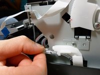
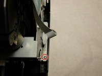
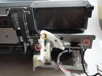
Remove the CD-R unit housing. Release the two attaching points to the tray base and then pull out the unit diagonally one side at a time.
-
-
-
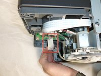
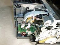
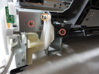
Detach the left frame support plate. Start by removing the two 6 mm screws that secure it and then pull it out by hand.
-
-
-
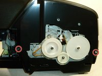
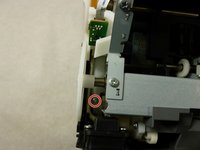
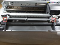
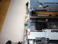
Remove the four 6 mm screws using the Phillips #2 screwdriver.
-
Remove the two 8 mm screw using a Phillips #2 screwdriver.
-
-
-
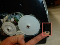
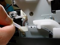
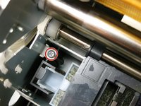
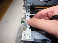
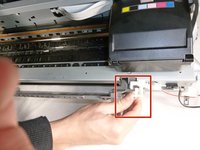
Pull out the two guide pins on the CD/DVD tray base.
-
-
-
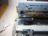
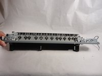
Remove the paper eject frame assembly by pulling it towards you.
-


To reassemble your device, follow these instructions in reverse order.
To reassemble your device, follow these instructions in reverse order.
crwdns2935221:0crwdne2935221:0
crwdns2935229:041crwdne2935229:0
crwdns2915084:0crwdne2915084:0

Cal Poly, Team 17-11, Regan Fall 2011 crwdns2935289:0Cal Poly, Team 17-11, Regan Fall 2011crwdne2935289:0
CPSU-REGAN-F11S17G11
crwdns2931471:04crwdne2931471:0
crwdns2935297:012crwdne2935297:0