crwdns2915892:0crwdne2915892:0
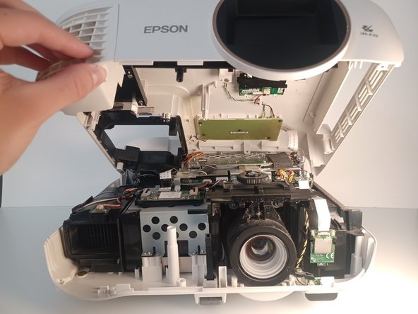
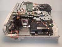
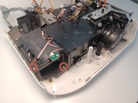
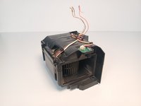
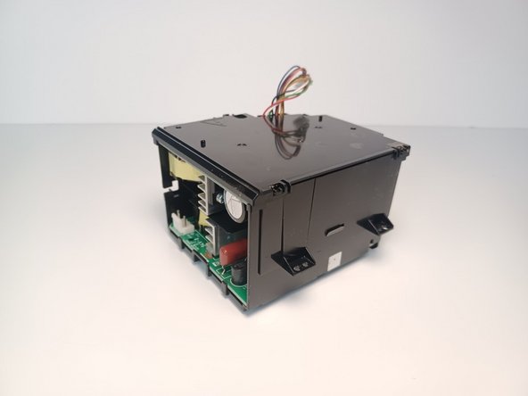
A replacement of the power supply unit is needed if the projector shows no sign of power despite the use of a functional power cable. It is located within the Epson Home Cinema 2150 almost at middle right next to the projector lens. It's a heavy black box.
The power supply is designed to deliver the proper power to the projector.
crwdns2942213:0crwdne2942213:0
-
-
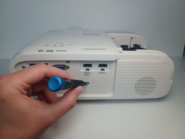
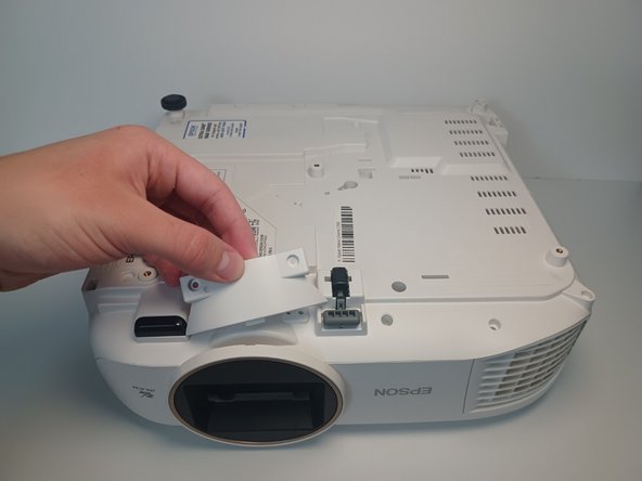
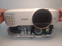
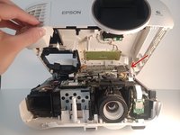
Orient the Epson Home Cinema 2150 so that the large indented panel faces your direction.
-
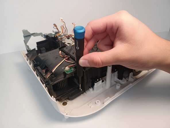
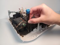
Unscrew the single 6mm Phillips#2 holding screw from the access panel.
-
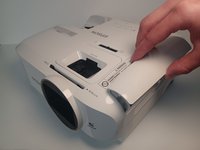
Slide the panel horizontally, then lift up to remove the access panel.
-
-
-
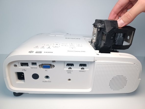
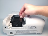
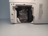
Loosen and remove the two screws holding the lamp.
-
Remove two 9 mm Phillips #2 screws.
-
-
-
Using four fingers, pull upwards on the lamp's plastic casing.
-
-
-
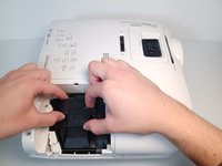
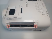
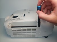
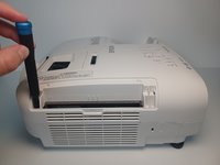
Remove the air filter cover. Grip the piece with two fingers above and below at the center.
-
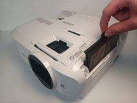
Grab the air filter from the protruding tab and pull the filter out.
-
-
-
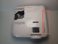
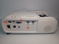
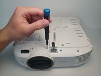
From the back of the projector remove three 6 mm Phillips #1 screws.
-
-
-
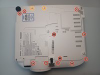
From the device's underside, remove eleven 9.5 mm Phillips #1 screws.
-
Remove two 6 mm Phillips #1 screws.
-
Pull off remaining plastic molding.
-
-
-
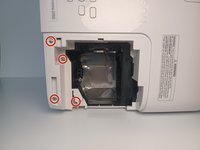
From the lamp access slot, remove four 9.5 mm Philips #1 screws
-
-
-
From the filter slot, unscrew two 9.5 mm #1 screws.
-
-
-
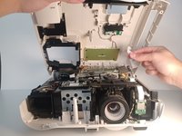
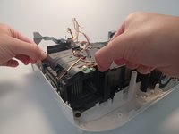
Partially lift the top portion of the device housing.
-
-
-
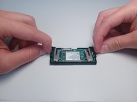
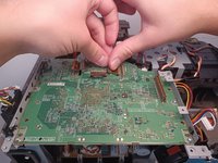
Disconnect the ribbon cable from the motherboard.
-
-
-
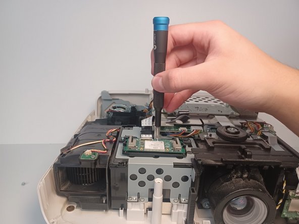
Remove three 5 mm Phillips #1 screws.
-
-
-
-
Press on the metal connector and firmly pull on the remaining ribbon cable.
-
-
-
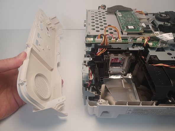
Pull the clips on the case with two fingers on opposite ends and remove the case.
-
-
-
Pull up on the rear panel retaining clip.
-
Pull the rear panel away from the device to remove.
-
-
-
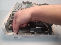
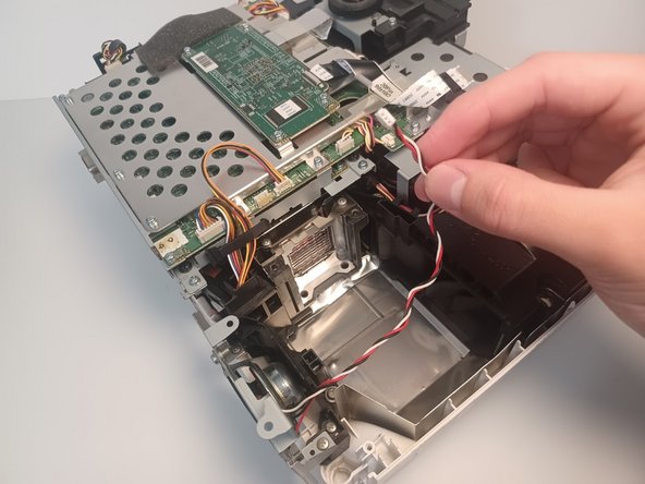
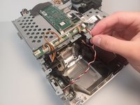
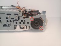
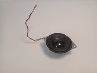
Disconnect the speaker wire from the motherboard.
-
-
-
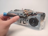
Unwind the speaker wire through the metal chassis.
-
-
-
Remove two 6 mm Phillips #1 screws.
-
Remove two 5 mm Phillips #1 screws.
-
-
-
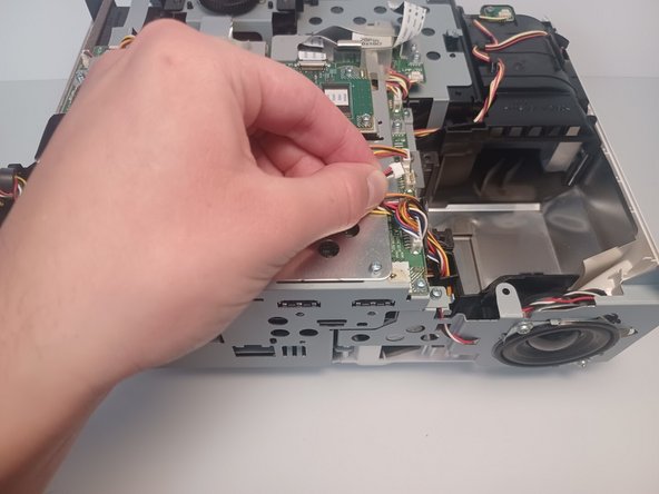
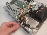
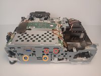
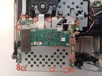
Disconnect a total of 10 motherboard connections.
-
-
-
Press on the metal connector and firmly pull to remove the remaining ribbon cable.
-
-
-
Remove twelve 5 mm Phillips #1 screws.
-
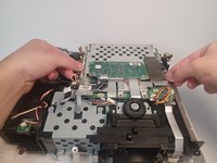
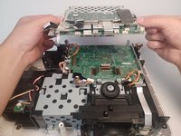
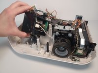
Using both hands, carefully lift the first half of the motherboard.
-
-
-
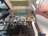
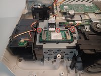
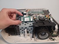
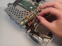
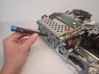
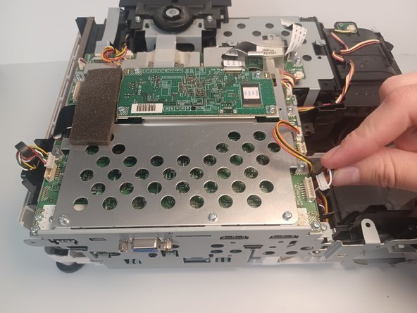
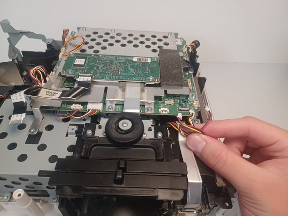
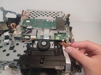
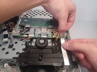
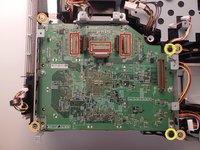
Disconnect the three brown ribbon connectors from the board.
-
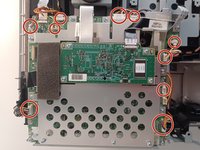
Remove four 5 mm Phillips #1 screws.
-
Remove two 3 mm Phillips #1 screws.
-
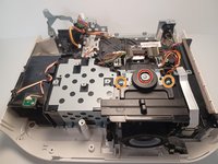
Pull upwards on the motherboard to remove it from the projector.
-
-
-
Remove the 7.5 mm Phillips #1 screw.
-
Remove two 6 mm Phillips #1 screws.
-
Set the black plastic lens sliders to the side.
-
-
-
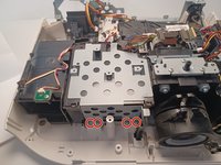
Remove five 9.5 mm Phillips #1 screws.
-
Remove one 6.0 mm Phillips #2 screw.
-
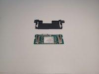
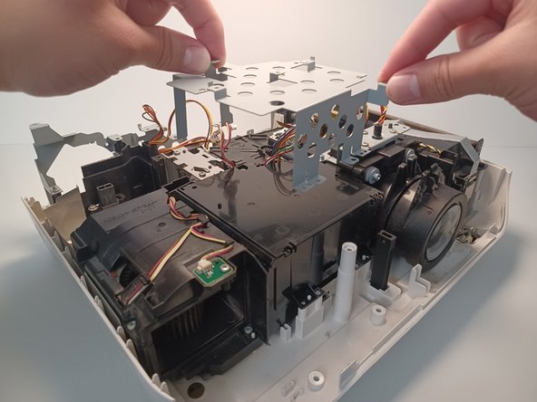
Remove the metal bracket by pulling upwards on its sides.
-
-
-
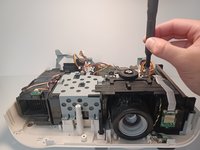
Remove the 9.5 mm Phillips #1 screw located behind the power supply.
-
Remove the 10 mm Phillips #1 screw.
-
-
-
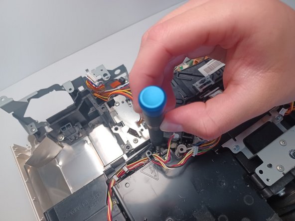
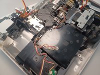
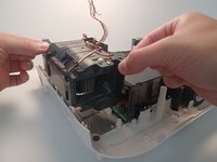
Move the fan cable to the side for clear access to the sensor below it.
-
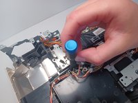
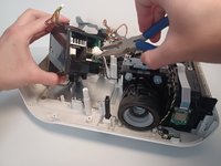
Using pliers, pull upwards on the white sensor to remove it from the fan assembly.
-
-
-
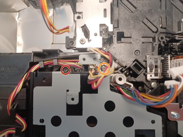
Remove two 9.5mm Phillips #1 screws.
-
-
-
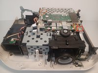
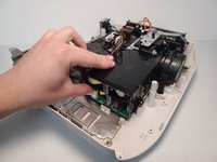
Carefully lift upwards on the fan assembly to remove the fan from the projector.
-
-
-
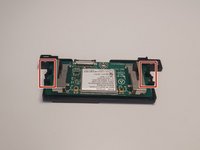
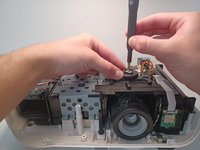
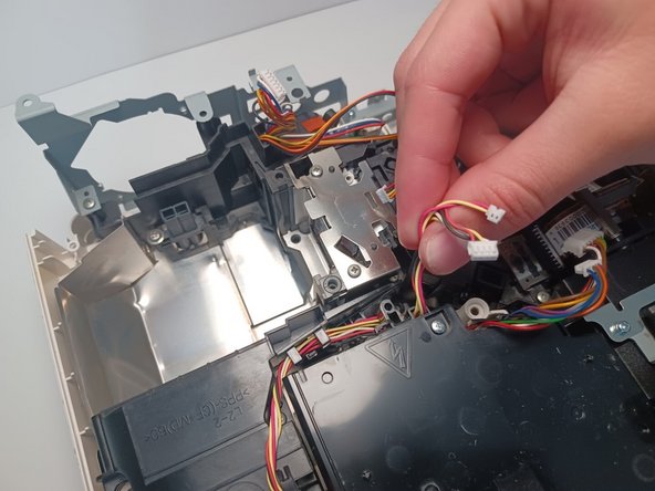
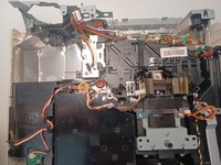
The power supply unit is a black box. Inside, there are two connected circuit boards, each with a single connector.
-
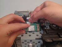
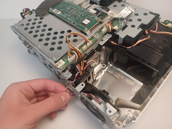
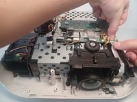
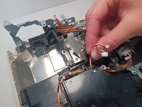
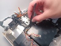
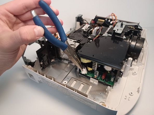
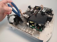
Using needle nose pliers, disconnect the first white connection cable from the circuit board.
-
-
-
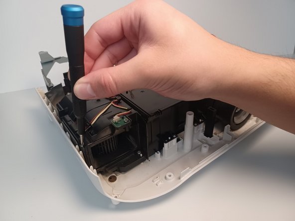
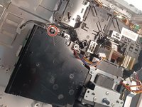
From the rear side of the power supply unit, remove a single 9.5 mm Phillips #1 screw.
-
-
-
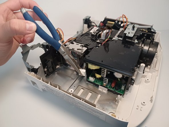
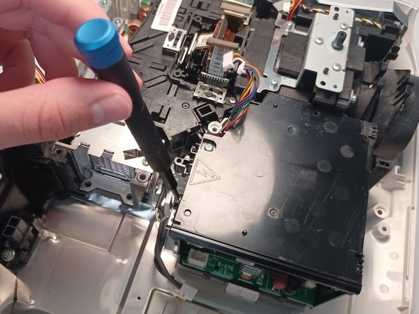
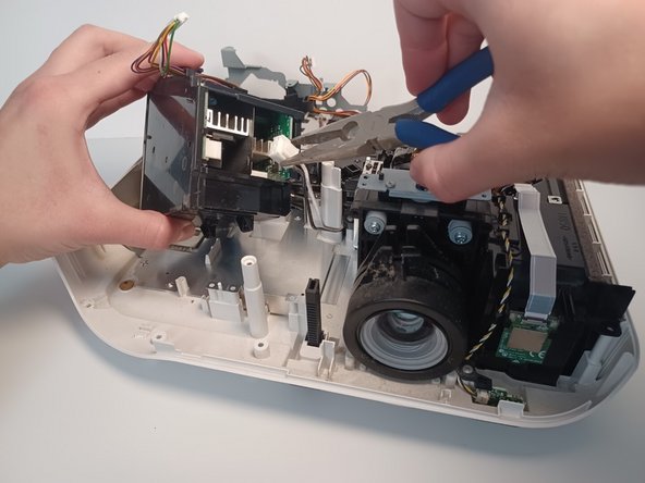
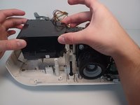
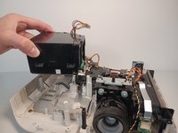
Carefully lift the power supply unit 2-3 inches upwards without creating tension on the remaining wires.
-
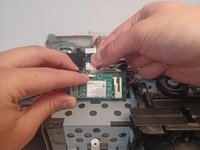
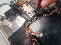
Angle the power supply unit to the side for clear access to the remaining connector.
-
Using needle nose pliers, disconnect the remaining wires from the power supply connector.
-


To reassemble your device, follow these instructions in reverse order.
To reassemble your device, follow these instructions in reverse order.
crwdns2935221:0crwdne2935221:0
crwdns2935227:0crwdne2935227:0

crwdns2915084:0crwdne2915084:0

CSU Los Angeles, Team 6-2, Adachi Fall 2022 crwdns2935289:0CSU Los Angeles, Team 6-2, Adachi Fall 2022crwdne2935289:0
CSULA-ADACHI-F22S6G2
crwdns2931471:04crwdne2931471:0
crwdns2935297:05crwdne2935297:0