crwdns2915892:0crwdne2915892:0
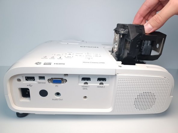
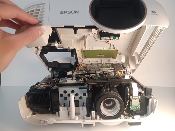
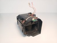
Fans are a mechanical component subject to wear and tear. Mechanical components are often the first to fail. In the event the exhaust fan within the projector begins to emit unpleasant noises, the exhaust fan may need to be replaced.
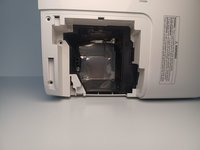
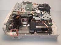
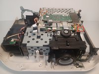
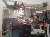
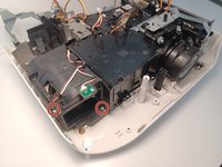
It is located inside the projector on the same row as the projector lens, all the way to the left, next to the power supply.
crwdns2942213:0crwdne2942213:0
-
-
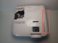
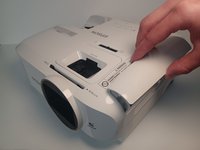
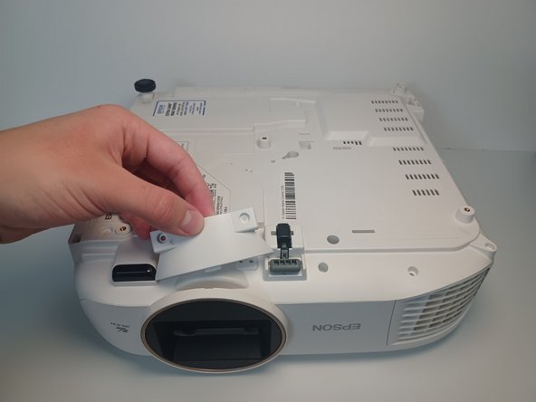
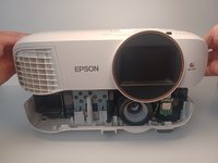
Orient the Epson Home Cinema 2150 so that the large indented panel faces your direction.
-
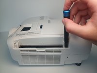
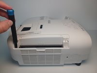
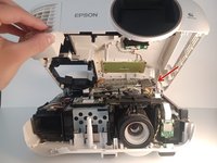
Unscrew the single 6mm Phillips#2 holding screw from the access panel.
-
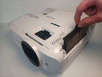
Slide the panel horizontally, then lift up to remove the access panel.
-
-
-
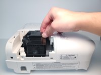
Loosen and remove the two screws holding the lamp.
-
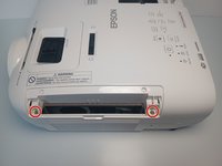
Remove two 9 mm Phillips #2 screws.
-
-
-
Using four fingers, pull upwards on the lamp's plastic casing.
-
-
-
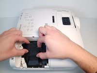
Remove the air filter cover. Grip the piece with two fingers above and below at the center.
-
Grab the air filter from the protruding tab and pull the filter out.
-
-
-
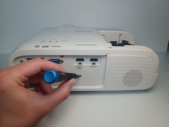
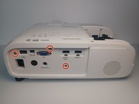
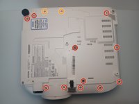
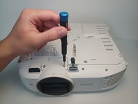
From the back of the projector remove three 6 mm Phillips #1 screws.
-
-
-
From the device's underside, remove eleven 9.5 mm Phillips #1 screws.
-
Remove two 6 mm Phillips #1 screws.
-
Pull off remaining plastic molding.
-
-
-
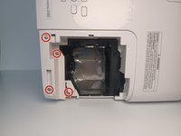
From the lamp access slot, remove four 9.5 mm Philips #1 screws
-
-
-
From the filter slot, unscrew two 9.5 mm #1 screws.
-
-
-
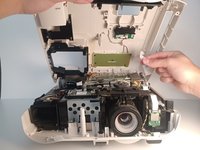
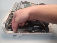
Partially lift the top portion of the device housing.
-
-
-
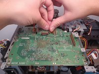
Disconnect the ribbon cable from the motherboard.
-
-
-
-
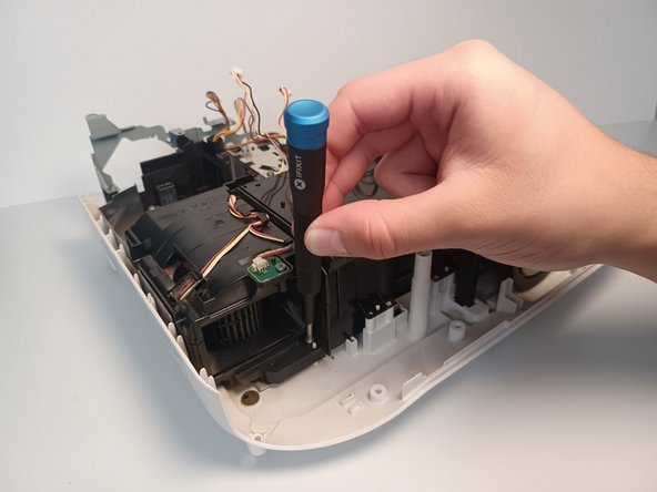
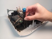
Remove three 5 mm Phillips #1 screws.
-
-
-
Press on the metal connector and firmly pull on the remaining ribbon cable.
-
-
-
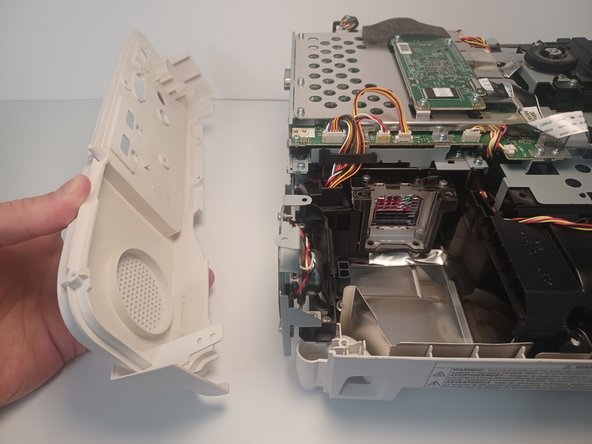
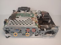
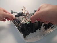
Pull the clips on the case with two fingers on opposite ends and remove the case.
-
-
-
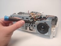
Pull up on the rear panel retaining clip.
-
Pull the rear panel away from the device to remove.
-
-
-
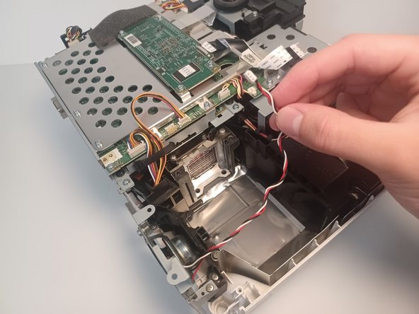
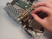
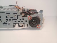
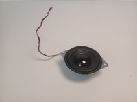
Disconnect the speaker wire from the motherboard.
-
-
-
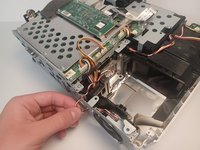
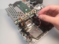
Unwind the speaker wire through the metal chassis.
-
-
-
Remove two 6 mm Phillips #1 screws.
-
Remove two 5 mm Phillips #1 screws.
-
-
-
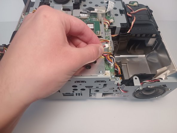
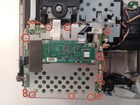
Disconnect a total of 10 motherboard connections.
-
-
-
Press on the metal connector and firmly pull to remove the remaining ribbon cable.
-
-
-
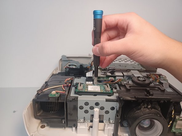
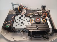
Remove twelve 5 mm Phillips #1 screws.
-
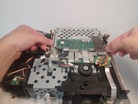
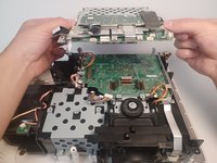
Using both hands, carefully lift the first half of the motherboard.
-
-
-
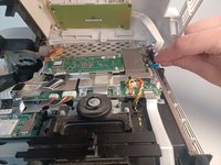
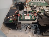
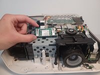
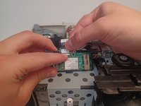
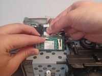
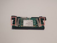
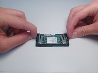
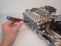
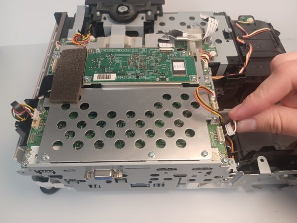
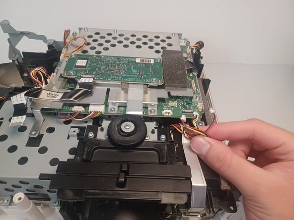
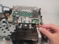
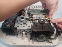
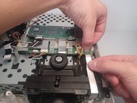
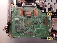
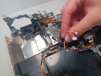
Disconnect the three brown ribbon connectors from the board.
-
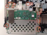
Remove four 5 mm Phillips #1 screws.
-
Remove two 3 mm Phillips #1 screws.
-
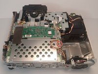
Pull upwards on the motherboard to remove it from the projector.
-
-
-
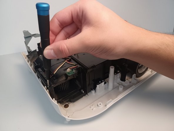
Remove the 7.5 mm Phillips #1 screw.
-
Remove two 6 mm Phillips #1 screws.
-
Set the black plastic lens sliders to the side.
-
-
-
Remove five 9.5 mm Phillips #1 screws.
-
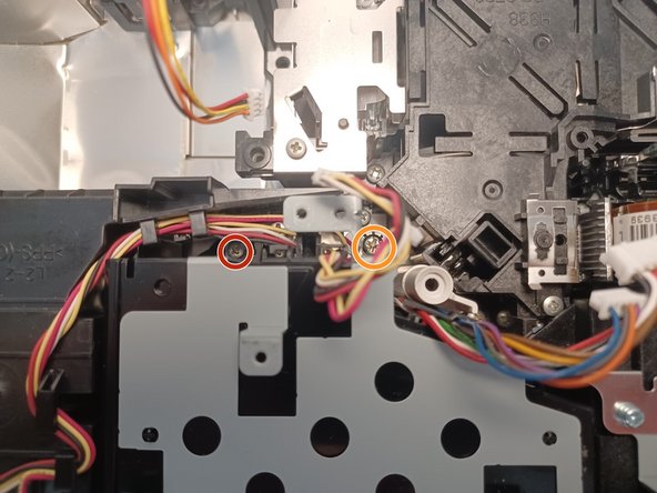
Remove one 6.0 mm Phillips #2 screw.
-
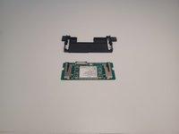
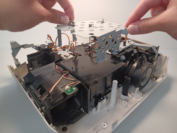
Remove the metal bracket by pulling upwards on its sides.
-
-
-
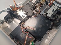
Remove the 9.5 mm Phillips #1 screw located behind the power supply.
-
Remove the 10 mm Phillips #1 screw.
-
-
-
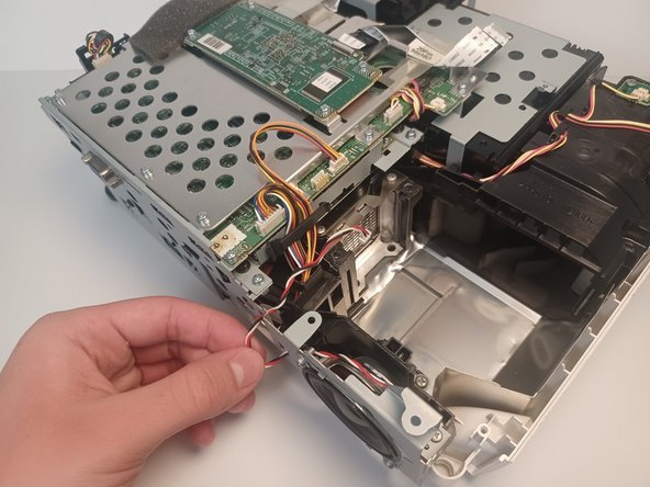
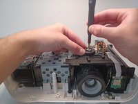
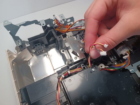
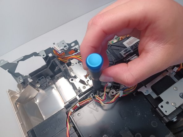
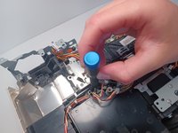
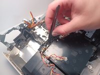
Move the fan cable to the side for clear access to the sensor below it.
-
Using pliers, pull upwards on the white sensor to remove it from the fan assembly.
-
-
-
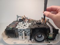
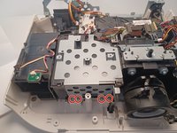
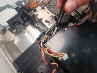
Remove two 9.5mm Phillips #1 screws.
-
-
-
Carefully lift upwards on the fan assembly to remove the fan from the projector.
-


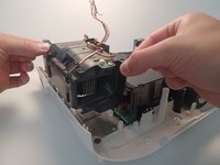
To reassemble your device, follow these instructions in reverse order.
crwdns2935221:0crwdne2935221:0
crwdns2935227:0crwdne2935227:0

crwdns2935287:0crwdne2935287:0

CSU Los Angeles, Team 6-2, Adachi Fall 2022 crwdns2935289:0CSU Los Angeles, Team 6-2, Adachi Fall 2022crwdne2935289:0
CSULA-ADACHI-F22S6G2
crwdns2931471:04crwdne2931471:0
crwdns2935297:05crwdne2935297:0