crwdns2915892:0crwdne2915892:0
Is your EGO electric mower no longer pulling its weight—literally? If the self-propelled function has stopped working or is making strange noises, it may be time to replace the self-propelled drive unit. This guide will walk you step-by-step through the process of replacing the self-propelled unit in your EGO electric mower, restoring its ability to climb hills and cruise across your lawn with ease. Whether you’re dealing with a failed motor, worn-out gears, or just want to extend the life of your mower, this repair is a practical way to get back up and running without replacing the whole machine.
crwdns2942213:0crwdne2942213:0
-
-
Before beginning any repairs, remove the battery from the mower and ensure the unit is completely powered off. This prevents accidental startups during disassembly.
-
Additionally, use caution when working around the blade area, even if the mower is powered down. The blades are sharp and can cause injury if handled carelessly. Wearing gloves is recommended for added protection.
-
-
-
To remove the self-propelled drive unit, you’ll first need to unplug it from power—this requires removing the mower’s rear cover.
-
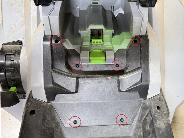
Using a T20 Torx screwdriver, remove the six screws that secure the rear cover in place. The screws are located around the perimeter of the cover (see image for reference).
-
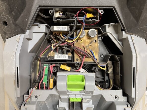
Once all screws are removed, gently lift the cover upward to detach it. It may take a bit of wiggling if there’s any debris or resistance.
-
-
-
-
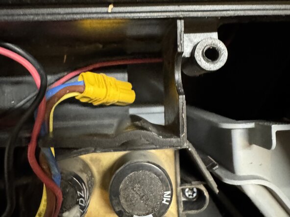
Next, unplug the power connection for the self-propelled drive unit. This is the triangular yellow connector with yellow, brown, and blue wires (refer to the image for reference).
-
Carefully remove the wire from the plastic channel that secures it in place.
-
Once free, gently push the wire down through the opening at the bottom of the compartment. This will allow the wiring to be free and make it easier to remove the self-propelled unit later.
-
After the connector is unplugged and routed out of the way, it's a good idea to reinstall the rear cover temporarily. The battery door has no locking mechanism and may get damaged when flipping the mower over in the next step.
-
-
-
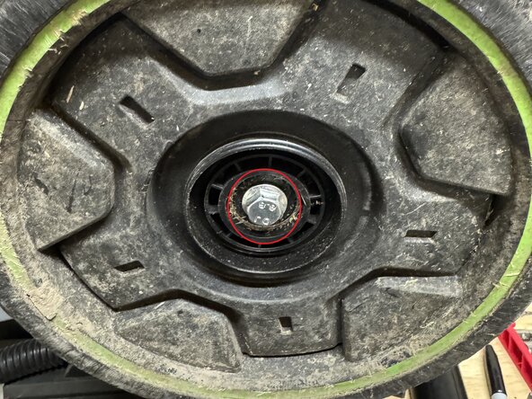
Start by flipping the lawn mower over. This will enable you to work on the Self-Propelled Unit in full.
-
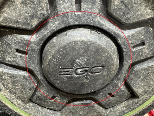
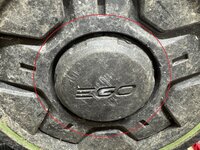
Remove the rear wheel hubcaps (see image for reference). These can be gently pried off using a tool of your choice—a flathead screwdriver works well.
-
Using a 13 mm socket with a ratchet or wrench, remove the axle nut from each wheel.
-
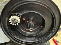
Carefully slide each wheel off the axle. You may feel slight resistance—this is normal, as the wheels house two sets of internal gears that may cause minor binding. There will also be a wave washer that is behind the wheel; this will also need to be removed.
-
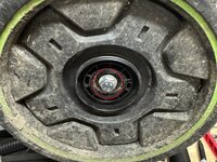
Once the wheels are off, remove the Protective Cap located behind them. These are held in place with a single Phillips screw.
-
-
-
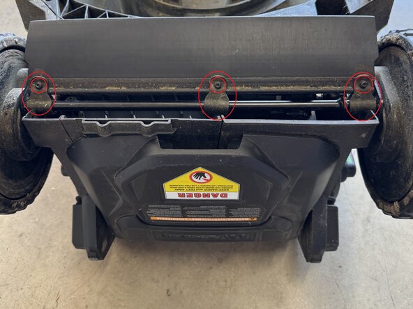
The Trail Shield is secured by three plastic Bevel Support clips, each of which snaps over the axle and is held in place with a T20 Torx screw through the Trail Shield.
-
Using a T20 Torx driver, remove the three screws (see image for reference).
-
Once the screws are removed, pull the rubber trail shield out, then slide the plastic clips off the axle.
-
-
-
Adjust the mower’s cut height to its highest setting. This raises the black axle bar and gives you better access to the mounting hardware.
-
Locate the 10mm Nyloc nut securing the axle to the height adjustment arm. Remove this nut using a 10mm wrench.
-
Once the nut is removed, slide out the welded bolt and allow the axle to rest gently at the base of the mower.
-
Next, remove the four T20 screws—two on each side—that hold the silver retention brackets in place. These brackets secure the drive unit laterally.
-
Finally, remove the two T20 screws that hold the motor itself to the mower. These screws include washers, so take care not to lose them during removal.
-


To reassemble your device, follow these instructions in reverse order.
crwdns2935221:0crwdne2935221:0
crwdns2935229:04crwdne2935229:0

crwdns2947412:02crwdne2947412:0
Almost perfect, at least close enough for me.
Thanks for the comment! I’d love to know what you think could be improved so I can update the guide.