crwdns2933423:0crwdne2933423:0

Disassembling Insignia Flex 8 Circuit Board

crwdns2942213:0crwdne2942213:0

  1. Disassembling Insignia Flex 8 Circuit Board, Circuit Board: crwdns2935265:01crwdnd2935265:01crwdnd2935265:01crwdne2935265:0
    • Turn off the power to your tablet to avoid injury.

    • Position the tablet so that the screen is face down and the power button is located in the upper left hand corner.

    • Hold down the power button for five seconds until the tablet powers down.

  2. Disassembling Insignia Flex 8 Circuit Board: crwdns2935265:02crwdnd2935265:01crwdnd2935265:02crwdne2935265:0 Disassembling Insignia Flex 8 Circuit Board: crwdns2935265:02crwdnd2935265:02crwdnd2935265:02crwdne2935265:0
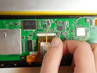
    • Remove the back casing from the screen by sliding a credit card or a similarly thin but firm object in between the casing and the screen.

    • You may need to use a spudger to initially create separation between the screen and the casing.

    • Run this object around the perimeter of the tablet until there is separation between the casing and the screen.

    • Remove the back casing and set aside.

  3. Disassembling Insignia Flex 8 Circuit Board: crwdns2935265:03crwdnd2935265:01crwdnd2935265:02crwdne2935265:0 Disassembling Insignia Flex 8 Circuit Board: crwdns2935265:03crwdnd2935265:02crwdnd2935265:02crwdne2935265:0
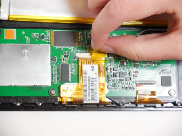
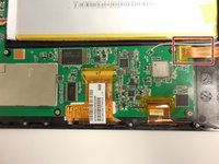
    • Peel tape off of ribbon connectors. Starting at the power button, work clockwise around the tablet.

  4. Disassembling Insignia Flex 8 Circuit Board: crwdns2935265:04crwdnd2935265:01crwdnd2935265:03crwdne2935265:0 Disassembling Insignia Flex 8 Circuit Board: crwdns2935265:04crwdnd2935265:02crwdnd2935265:03crwdne2935265:0 Disassembling Insignia Flex 8 Circuit Board: crwdns2935265:04crwdnd2935265:03crwdnd2935265:03crwdne2935265:0
    • To remove the camera ribbon cable, lift the flap using a spudger.

    • Pull the ribbon directly back to release it.

  5. Disassembling Insignia Flex 8 Circuit Board: crwdns2935265:05crwdnd2935265:01crwdnd2935265:03crwdne2935265:0 Disassembling Insignia Flex 8 Circuit Board: crwdns2935265:05crwdnd2935265:02crwdnd2935265:03crwdne2935265:0 Disassembling Insignia Flex 8 Circuit Board: crwdns2935265:05crwdnd2935265:03crwdnd2935265:03crwdne2935265:0
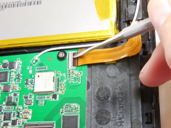
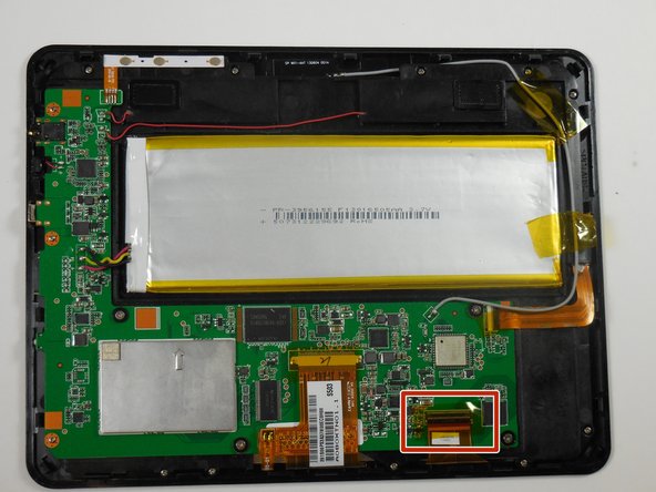
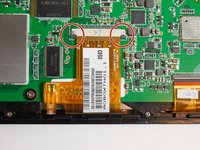
    • Remove the second ribbon cable by prying up the black flap using a spudger.

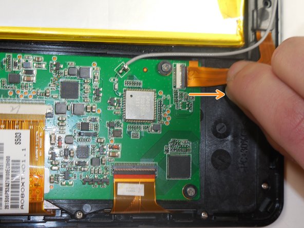
    • Pull the ribbon cable horizontally directly away from the battery.

  6. Disassembling Insignia Flex 8 Circuit Board: crwdns2935265:06crwdnd2935265:01crwdnd2935265:03crwdne2935265:0 Disassembling Insignia Flex 8 Circuit Board: crwdns2935265:06crwdnd2935265:02crwdnd2935265:03crwdne2935265:0 Disassembling Insignia Flex 8 Circuit Board: crwdns2935265:06crwdnd2935265:03crwdnd2935265:03crwdne2935265:0
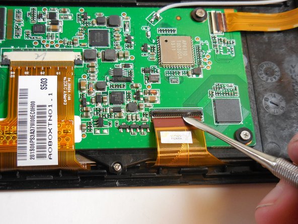
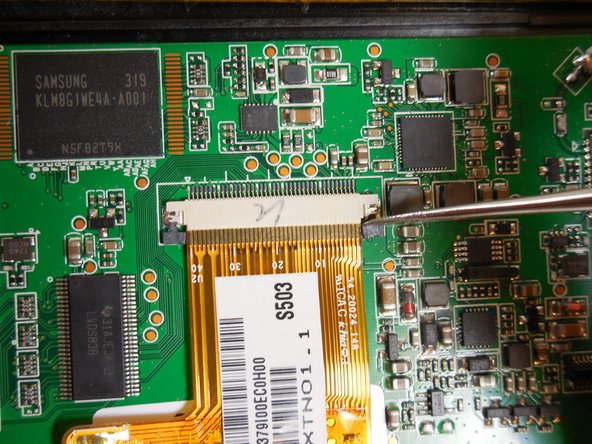
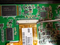
    • Remove the final ribbon cable by pulling back the two black tabs on either side of the ribbon cable.

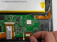
    • Pull the ribbon horizontally directly away from the battery.

  7. Disassembling Insignia Flex 8 Circuit Board: crwdns2935265:07crwdnd2935265:01crwdnd2935265:02crwdne2935265:0 Disassembling Insignia Flex 8 Circuit Board: crwdns2935265:07crwdnd2935265:02crwdnd2935265:02crwdne2935265:0
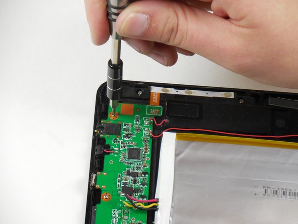
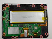
    • Unscrew the thirteen 4.75mm screws around the perimeter of the tablet using a PH 00 screwdriver.

  8. Disassembling Insignia Flex 8 Circuit Board: crwdns2935265:08crwdnd2935265:01crwdnd2935265:02crwdne2935265:0 Disassembling Insignia Flex 8 Circuit Board: crwdns2935265:08crwdnd2935265:02crwdnd2935265:02crwdne2935265:0
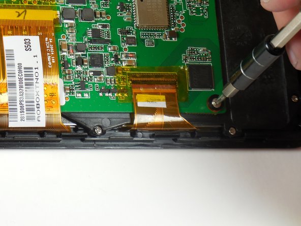
    • Unscrew the four 3.75mm screws and plastic washers using a PH 00 screwdriver.

    • Lift up the circuit board.

  9. Disassembling Insignia Flex 8 Circuit Board: crwdns2935265:09crwdnd2935265:01crwdnd2935265:01crwdne2935265:0
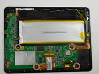
    • Unscrew the final two screws that were underneath the circuit board.

    • These screws are near the charging port and USB adapter.

    • These screws are also 3.75mm and can be interchanged with the second set of screws only.

  10. Disassembling Insignia Flex 8 Circuit Board: crwdns2935265:010crwdnd2935265:01crwdnd2935265:01crwdne2935265:0
    • Lift the circuit board and black internal mounting piece away from the screen.

    • Set the circuit board aside.

    • Be careful of the soldered antenna as you separate the pieces.

    • Be careful of the soldered ribbon that is connected to the power source. This ribbon is fragile.

    PHOTOS and DETAIL of the ANTENNA would help. Are the ANTENNA connections UNSOLDERED? The photo shows a DARKER ribbon cable ~ was that disconnected in a earlier step? Thank you... your post is giving me courage!

    wa6igj - crwdns2934203:0crwdne2934203:0

crwdns2915888:0crwdne2915888:0

To reassemble your device, follow these instructions in reverse order.

crwdns2935229:02crwdne2935229:0

Tyler Tyrrell

crwdns2935283:003/11/15crwdne2935283:0

890 crwdns2915208:0crwdne2915208:0

crwdns2935297:04crwdne2935297:0

crwdns2915084:0crwdne2915084:0

Colorado Springs, Team 5-5, Panko Spring 2015 crwdns2935289:0Colorado Springs, Team 5-5, Panko Spring 2015crwdne2935289:0

UCCS-PANKO-S15S5G5

crwdns2931471:03crwdne2931471:0

crwdns2935297:012crwdne2935297:0

crwdns2947412:02crwdne2947412:0

Whwre can i buy the new screen

Emmanuel - crwdns2934203:0crwdne2934203:0

I don’t see the ssd, and way to upgrade the internal sad had?

William Henderson - crwdns2934203:0crwdne2934203:0

crwdns2917038:0crwdne2917038:0

crwdns2936625:0crwdne2936625:0:

crwdns2936751:024crwdne2936751:0 0

crwdns2936753:07crwdne2936753:0 0

crwdns2936753:030crwdne2936753:0 10

crwdns2942667:0crwdne2942667:0 4,978