crwdns2915892:0crwdne2915892:0
When using an Oscilloscope, the most common way to connect to your DUT (Device Under Test) is to use an Oscilloscope Probe. Most Oscilloscopes come with a probe for each of its inputs. You typically only need to make this adjustment when first setting them up but it is a good idea to occasionally check them as a properly compensated probe gives you the most accurate signal image.
crwdns2942213:0crwdne2942213:0
-
-
Connect your Oscilloscope probe to the input channel you are going to use. The process is the same no matter what channel you use. For this demo I will use channel 1.
-
Connect the probe tip to the Oscilloscope calibration output (typically a square wave output on the front panel). Make sure to connect the probe tip to the signal output and the probe ground to the ground.
-
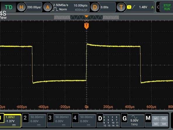
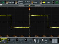
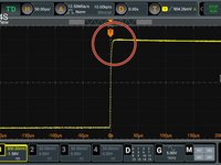
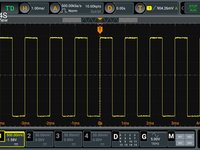
Adjust your scope trigger (or use auto on some models) and you should see a square wave as in the picture. The lack of flatness in the response (see circled spot) is what you are compensating for.
-
-
-
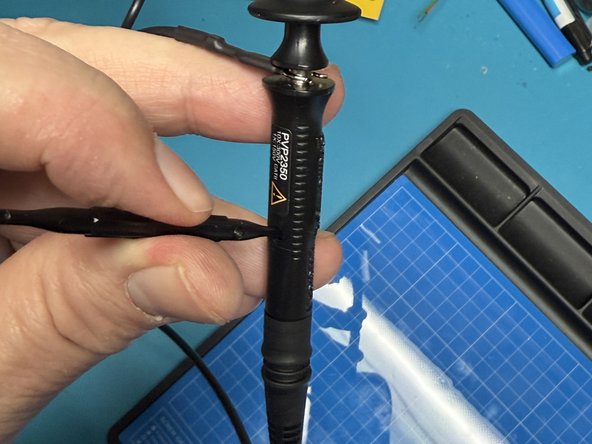
Locate the compensation adjustment on your probe. On some probes it is actually on the side of the probe as pictured, on others it can be on the base that plugs into the scope.
-
Locate the adjustment screwdriver that comes with the probe.
-
Insert the screwdriver into the adjustment hole as shown.
-
-
-
-
Adjust the screw while watching the display until you have the cleanest and flattest wave form.
-
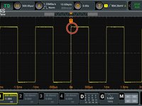
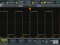
You can adjust the Oscilloscope Horizontal range to give you a better image to work with.
-
If you really open up the Horizontal width, you may see just a slight curve on the rise of the leading edge of the wave, that is fine as there is a slight lag on the rise time.
-
-
-
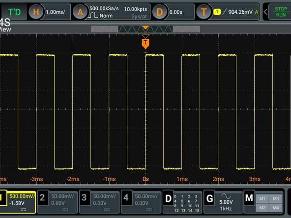
When properly compensated, you will have a nice level square wave displayed.
-
If you change the horizontal bandwidth of the scope, you should see the square wave stay flat across the top and bottom.
-
You are done. You are now ready to use your scope to look at signals for troubleshooting and circuit experimentation.
-


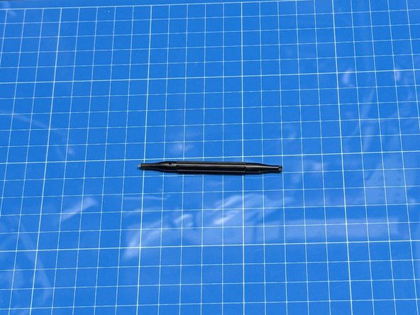


Your Oscilloscope probe typically comes in a package with the scope and contains clips, color markers, and a small screwdriver
Your Oscilloscope probe typically comes in a package with the scope and contains clips, color markers, and a small screwdriver
crwdns2935221:0crwdne2935221:0
crwdns2935227:0crwdne2935227:0
