crwdns2942213:0crwdne2942213:0
crwdns2936621:0crwdne2936621:0
-
-
Ensure the laptop is powered off .
-
Flip the laptop over.
-
-
-
Loosen the two Phillips head screws.
-
These screws should back out, but should not actually be removable.
-
Locate the indent on the rear cover half way between the two Phillips head screws.
-
Insert your spudger to help pry up the rear cover.
-
It may be necessary to run the spudger along the side with the indent to help release the clips
-
Lift off the rear cover.
-
-
-
-
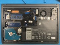
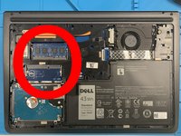
The RAM slots are in line with the hard drive, and on the right side if the cover was opened away from you.
-
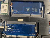
Please note that there are A and B RAM Slots. There must be a RAM chip in the A Slot, or the laptop will not load normally.
-
The Slots are labeled on the board, under where the chips would normally be seated.
-
-
-
Ensure that the space in the RAM chip lines up with alignment pin on the slot.
-
Insert the RAM chip at approximately at 45° angle.
-
Once the chip bottoms out on the slot, push down on the opposite side from the pins until the RAM chip seats on the board.
-
-
-
Depending on your machines current configuration, you may need to remove a RAM chip before you can insert your new ones.
-
Using your finger nail or a spudger, push the lock clips off the RAM chip.
-
Normally the clips can be done one at a time, but may require you to release both at once.
-
Once released, the chip should spring up and can be removed.
-


To reassemble your device, follow these instructions in reverse order.
crwdns2935221:0crwdne2935221:0
crwdns2935229:02crwdne2935229:0