crwdns2915892:0crwdne2915892:0
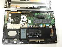
This system board is packed with NVIDIA Geforce MX150 and an Intel i5 or i7 Processor! Unfortunately it is not possible to remove these components from the system board.
crwdns2942213:0crwdne2942213:0
-
-
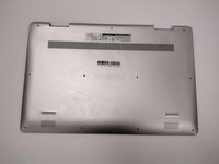
Remove the eight M2 5mm screws that secure the base cover using a Phillips #0 screwdriver.
-
-
-
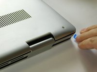
Loosen the three captive screws that secure the base closer to the hinges.
-
-
-
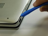
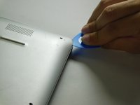
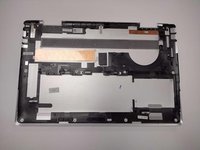
Carefully pry the base cover using an iFixit opening tool in the crevice near the hinges. Guide the pick along the edges and slightly lift upwards as you go along.
-
-
-
Carefully remove the base cover from the laptop.
-
-
-
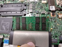
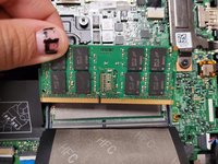
Lift the cover to gain access to the memory module.
-
-
-
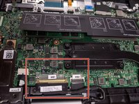
Carefully open the securing clips on the end of each memory module slot until the module stick sticks up.
-
-
-
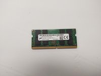
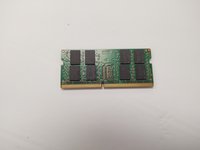
Remove the memory module by sliding it out of the slot.
-
-
-
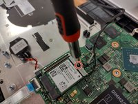
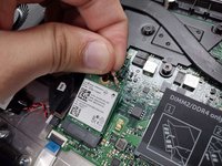
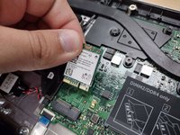
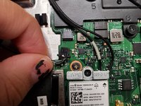
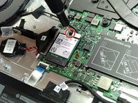
Remove the screw holding down the small bracket for the wireless card using a Phillips #0 screwdriver.
-
Remove the black wired connection from the port over the black triangle.
-
Remove the wire with the white marking from the port above the white triangle.
-
Pull the Wi-Fi card out of its slot.
-
-
-
-
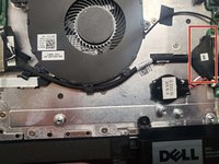
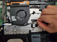
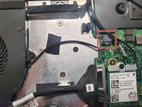
Remove the fan cable from the motherboard.
-
-
-
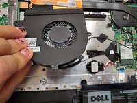
Remove two 3 mm screws that secure the fan using a Phillips #0 screwdriver.
-
-
-
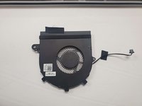
Lift the fan off the palm rest assembly.
-
-
-
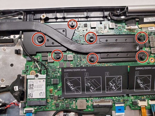
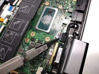
Loosen seven 3 mm captive screws securing the heatsink to the motherboard using a Phillips #0 screwdriver.
-
-
-
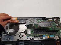
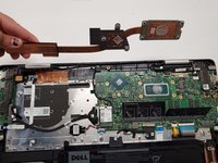
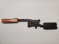
Lift the heatsink off the motherboard.
-
-
crwdns2935267:0crwdne2935267:0Tweezers$4.99
-
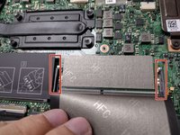
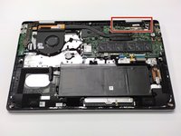
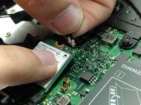
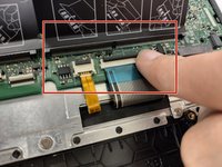
Locate the ribbon cables for the assembly on the right hand side marked "MB1" and "MB2."
-
The "MB1" ribbon is locked with a copper/brass colored handle that must be lifted upwards. Then you can remove the ribbon by pulling it away from the socket.
-
The "MB2" ribbon is locked in its socket with a black latch. Using a non-metallic precision tool (such as tweezers) lift the latch and pull away the MB2 cable.
-
-
-
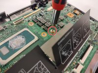
Remove the two screws holding down the assembly on the right hand area using a Phillips #00 screwdriver.
-
-
-
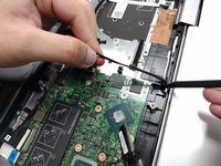
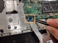
Remove the screw protecting the endpoints of the NIC cables and NIC chip using a Phillips #0 screwdriver.
-
Gently pull away the cabling from the NIC chip.
-
-
-
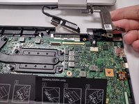
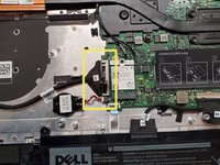
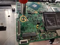
Remove the two screws holding down the bracket of the assembly on the left hand side using a Phillips #0 screwdriver.
-
-
-
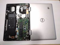
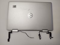
Lift the display assembly upwards away from the palm/main assembly.
-
-
-
Disconnect all cables from the system board:
-
Keyboard cables with latches
-
HDD cable with latch
-
I/O cable that must be lifted or carefully pried away from the board using a spudger
-
-
-
Disconnect the touch pad cable with the latch.
-
-
-
Remove the two screws holding down the system board using a Phillips #0 screwdriver:
-
One screw is located above the RAM slot to the right.
-
Another screw is located next to the I/O cable near the edge on the left.
-
Lift the motherboard out of the laptop.
-


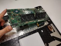
To reassemble your device, follow these instructions in reverse order.
To reassemble your device, follow these instructions in reverse order.

crwdns2915084:0crwdne2915084:0

Gateway, Team 1-3, Class Fall 2022 crwdns2935289:0Gateway, Team 1-3, Class Fall 2022crwdne2935289:0
GCC-CLASS-F22S1G3
crwdns2931471:04crwdne2931471:0
crwdns2935297:015crwdne2935297:0