crwdns2915892:0crwdne2915892:0
This guide shows the process of removing the keyboard from the Dell Inspiron 15-7547.
crwdns2942213:0crwdne2942213:0
-
-
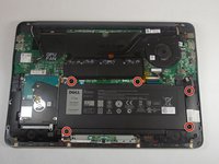
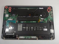
Close the display and flip the laptop on its back.
-
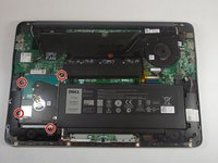
Loosen the ten 5.0 mm-long Phillips #0 screws.
-
The four screws marked with orange will remain captive to the cover.
-
-
-
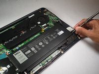
Use a spudger to pry up and loosen the back cover.
-
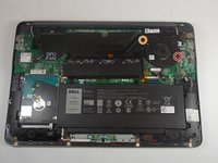
Remove the back cover.
-
-
-
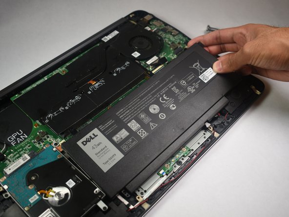
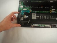
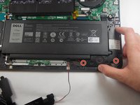
Remove the five 5.0 mm-long Philips #0 screws that connect the battery to the case.
-
-
-
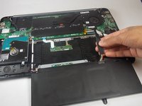
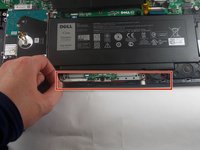
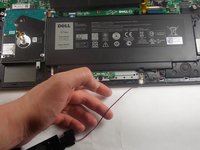
Pull the battery cable's pull tab towards the battery to disconnect it from the motherboard.
-
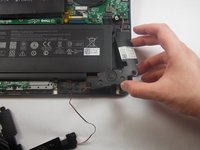
Remove the battery.
-
-
-
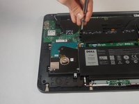
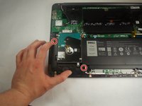
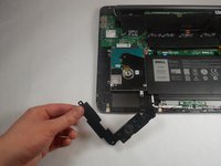
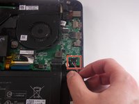
Remove the four 5.0 mm-long Philips #0 screws connecting the hard drive to the chassis.
-
-
-
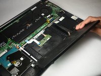
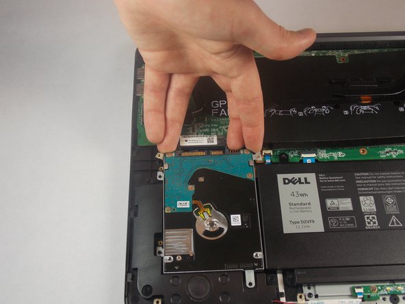
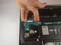
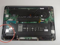
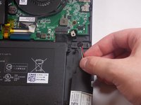
Disconnect the hard drive from the motherboard by placing your fingers at the back, and pulling forward towards the front of the chassis.
-
-
-
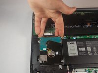
Lift the hard drive out of the chassis.
-
-
-
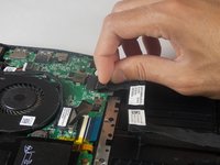
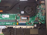
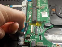
Remove the 3.0 mm-long Philips #0 screw at the end of the Wifi-Card
-
-
-
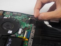
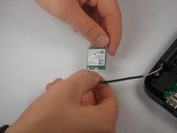
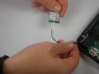
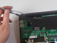
Remove the Wifi-Card from its socket by pulling away and up from the connector.
-
-
-
Disconnect the white and black cables from the Wifi-Card.
-
-
-
Orient the computer so that the hinge for the display facing away from you.
-
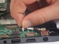
Start removing the speaker on the left by pushing the speaker in the direction of the tick mark on the 2 outer pegs, then upwards
-
-
-
-
Remove the left speaker by pushing the speaker in the direction of the tick mark on the center peg, then upwards
-
-
-
Remove the wire connecting the left speaker to the right speaker.
-
-
-
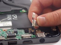
Start removing the right speaker by pushing the speaker in the direction of the tick marks on the 2 pegs closest to the front of the device, and then upwards.
-
-
-
Remove the right speaker by pushing in the direction of the tick mark on the final peg, and then upwards.
-
-
-
Remove the cable connecting the right speaker to the motherboard by pulling towards the front of the device.
-
-
-
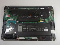
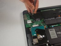
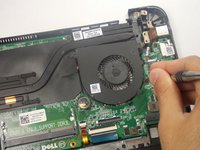
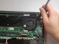
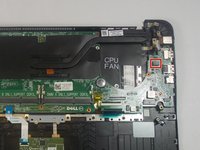
Remove the two 5.0 mm-long Philips #0 screws from the fan.
-
The screw marked in orange will remain captive to the fan.
The top left screw did come out, watch for the display wire that is underneath some metal tags on the fan.
-
-
-
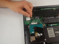
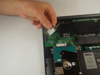
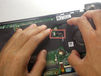
Disconnect the wire that connects the fan to the motherboard. This can be found under the flap directly to the left of the fan.
-
-
-
Remove the six 7.0 mm-long Philips #0 screws that mount the hinges.
-
-
-
Use a spudger to unlatch and unplug the display cable.
-
-
-
Remove the LCD display assembly from the laptop.
-
-
-
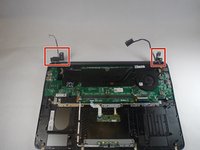
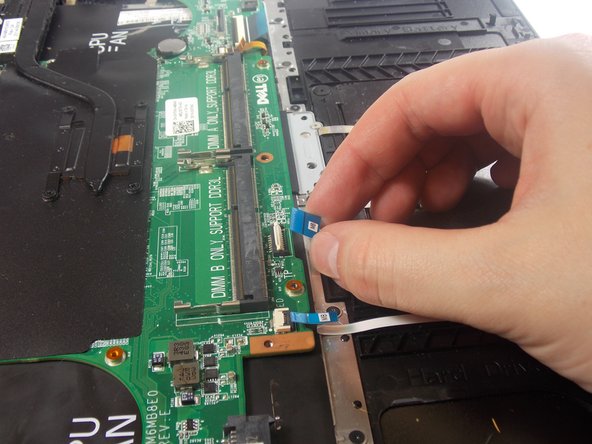
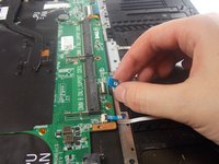
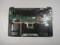
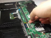
Unlatch the ribbon cable by pulling the white release up.
-
Hold the blue flap and pull to unplug the cable.
-
-
-
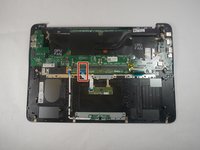
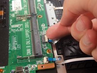
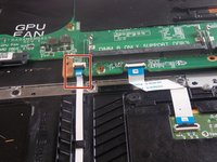
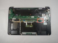
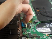
Unlatch black release on the ribbon cable.
-
Hold the blue flap to unplug the cable.
-
-
-
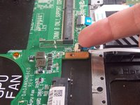
Unlatch the ribbon cable by pulling the black release up.
-
Hold the flap and unplug the cable.
-
-
-
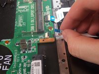
Unlatch the ribbon cable by pulling the black release up.
-
Hold the blue flap and unplug the cable.
-
-
-
Remove the seven 3.0 mm-long Philips #0 screws that secure the motherboard.
-
-
-
Remove the motherboard from the laptop.
-
-
-
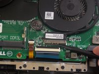
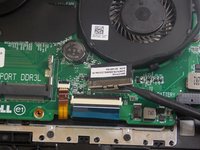
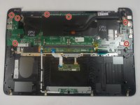
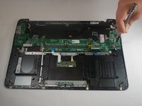
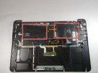
Remove the five 2.0 mm-long Philips #00 screws from the metal back-plate.
-
-
-
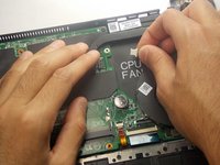
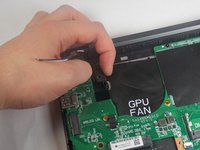
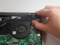
Peal away the two plastic covers marked GPU fan and CPU fan.
-
-
-
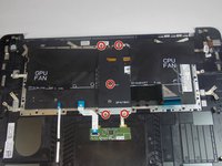
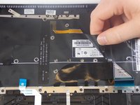
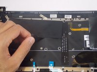
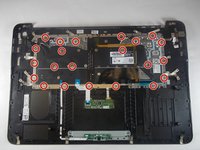
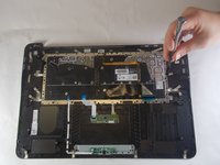
Remove the twenty-two 2.0 mm-long Philips #00 screws that connect the keyboard to the chassis.
-
-
-
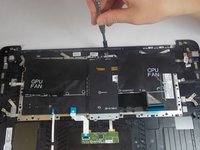
Lift the the keyboard from the chassis.
-


To reassemble your device, follow these instructions in reverse order.
To reassemble your device, follow these instructions in reverse order.
crwdns2935221:0crwdne2935221:0
crwdns2935227:0crwdne2935227:0
crwdns2915084:0crwdne2915084:0

Appalachian State University, Team S2-G4, Menagarishvili Fall 2018 crwdns2935289:0Appalachian State University, Team S2-G4, Menagarishvili Fall 2018crwdne2935289:0
APSU-MENAGARISHVILI-F18S2G4
crwdns2931471:03crwdne2931471:0
crwdns2935297:010crwdne2935297:0
crwdns2947410:01crwdne2947410:0
I'm trying to source the 22 , 2.0 mm-long screws that connect the keyboard to the chassis but I dont know what the correct specifications to look for, can someone please help?