crwdns2915892:0crwdne2915892:0
In this guide, we will be showing you how to replace the Heat-Sink Assembly.
crwdns2942213:0crwdne2942213:0
-
-
Close the display and turn the computer over.
-
-
-
Loosen the captive screws that secure the base panel to the computer base.
-
-
-
Using a plastic scribe, gently release the tabs that secure the base panel to the computer base.
-
-
-
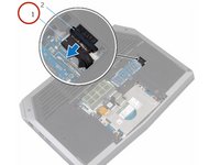
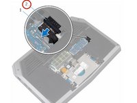
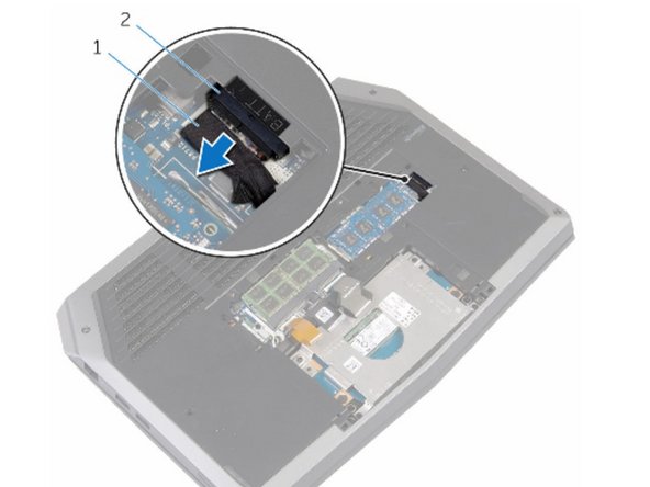
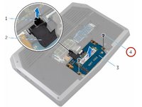
Disconnect the battery cable from the battery-cable connector.
-
Turn the computer over.
-
-
-
Press and hold the power button for 5 seconds to ground the system board.
-
-
-
Connect the battery cable to the battery-cable connector.
-
-
-
Align the tabs on the base panel with the slots on the computer base and snap the base panel into place.
-
-
-
Tighten the captive screws that secure the base panel to the computer base.
-
-
-
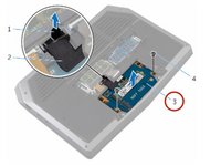
Remove the screws that secure the solid-state drive bracket to the solid-state drive assembly.
-
-
-
Using the pull tab, pivot the solid-state drive bracket and peel off the bracket from the tabs on the computer base.
-
-
-
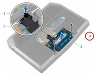
Using the pull tab, disconnect the solid-state drive cable from the system board.
-
-
-
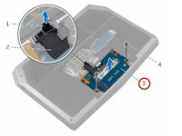
Remove the screws that secure the solid-state drive assembly to the computer base.
-
-
-
Lift the solid-state drive assembly off the computer base.
-
-
-
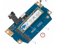
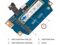
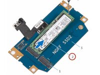
Remove the screw that secures the solid-state drive to the solid-state drive assembly.
-
-
-
Slide and lift the solid-state drive off the solid-state drive assembly.
-
-
-
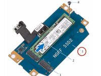
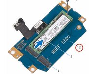
Slide the NEW solid-state drive into the slot on the solid-state drive assembly.
-
-
-
Replace the screw that secures the solid-state drive to the solid-state drive assembly.
-
-
-
Align the screw holes on the solid-state drive assembly with the screw holes on the computer base.
-
-
-
Replace the screws that secure the solid-state drive assembly to the computer base.
-
-
-
Connect the solid-state drive cable to the system board.
-
-
-
Align the screw holes on the solid-state drive bracket with the screw holes on the solid-state drive assembly.
-
-
-
Replace the screws that secure the solid-state drive bracket to the solid-state drive assembly.
-
-
-
Lift the latches and disconnect the keyboard and keyboard-backlight cables from the system board.
-
-
-
Remove the screws that secure the palm-rest assembly to the computer base.
-
-
-
Lift the computer base slightly and push the release tabs on the palm-rest assembly until it pops out.
-
-
-
Turn the computer over and open the display as far as possible.
-
-
-
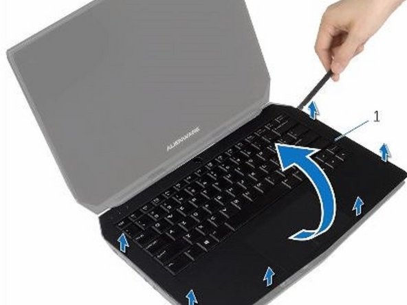
Using a plastic scribe, pry up along the edges of the palm-rest assembly.
-
-
-
Gently lift the palm-rest assembly and turn it over.
-
-
-
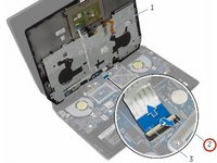
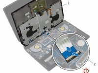
Lift the connector latch and disconnect the power-button board cable from the system board.
-
-
-
-
Lift the palm-rest assembly off the computer base.
-
-
-
Remove the keyboard.
-
Remove the power-button board.
-
Remove the status-light board.
-
Remove the Touchpad.
-
-
-
Replace the touchpad.
-
Replace the status-light board.
-
Replace the power-button board.
-
Replace the keyboard.
-
-
-
Connect the power-button board cable to the system board.
-
-
-
Align the palm-rest assembly on the computer base and snap it into place.
-
-
-
Close the display and turn the computer over.
-
-
-
Replace the screws that secure the palm-rest assembly to the computer base.
-
-
-
Connect the keyboard cable and the keyboard-backlight cable to the system board.
-
-
-
Open the display as far as possible.
-
-
-
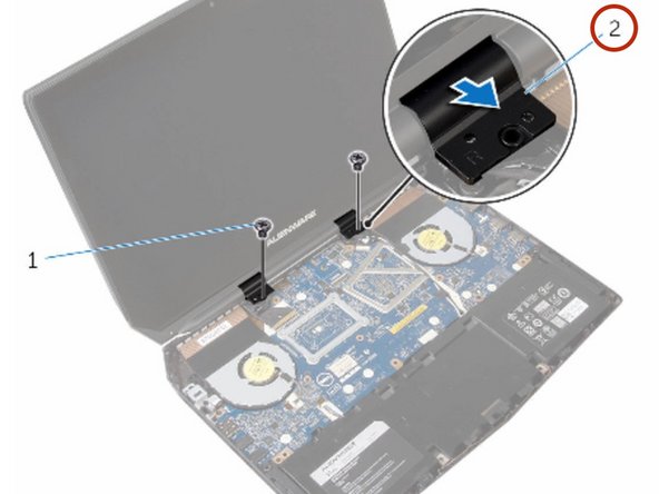
Remove the screws that secure the hinge caps to the display hinges.
-
-
-
Slide and lift the hinge caps off the display hinges.
-
-
-
Close the display and turn the computer over.
-
-
-
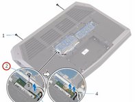
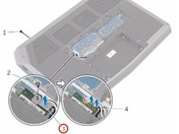
Remove the screw that secures the wireless-card bracket to the wireless card.
-
-
-
Disconnect the antenna cables from the wireless card.
-
-
-
Turn the computer over and open the display.
-
-
-
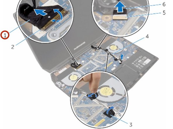
Remove the antenna cables from the routing guides on the display hinges.
-
-
-
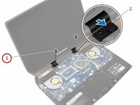
Lift the connector latch and disconnect the display cable from the system board.
-
-
-
Remove the display cable from the routing guides on the display hinges.
-
-
-
Disconnect the logo-board cable from the system board and remove it from the routing guides on the display hinges.
-
-
-
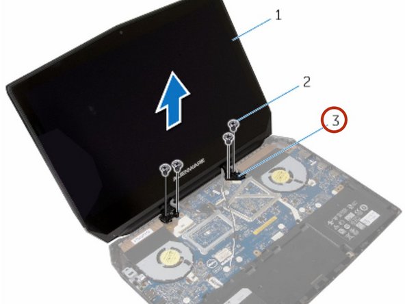
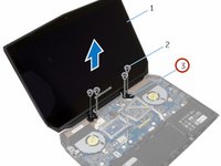
Remove the screws that secure the display assembly to the computer base.
-
-
-
Lift the display assembly off the computer base.
-
-
-
Align the screw holes on the display hinges with the screw holes on the computer base.
-
-
-
Replace the screws that secure the display hinges to the computer base.
-
-
-
Route the logo-board cable through the routing guides on the display hinge and connect the logo-board cable to the system board.
-
-
-
Route the display cable through the routing guides on the display hinge.
-
-
-
Slide the display cable into the connector on the system board and press down the latch to secure the cable.
-
-
-
Route the antenna cables through the routing guides on the display hinges.
-
-
-
Adhere the adhesive tapes that secure the antenna cables to the system board.
-
-
-
Close the display and turn the computer over.
-
-
-
Connect the antenna cables to the wireless card.
-
-
-
Replace the screw that secures the wireless-card bracket to the wireless card.
-
-
-
Turn the computer over and open the display.
-
-
-
Align the screw holes on the hinge caps with the screw holes on the display hinges.
-
-
-
Replace the screws that secure the hinge caps to the display hinges.
-
-
-
Remove the screw that secures the power-adapter port bracket to the power-adapter port.
-
-
-
Lift the power-adapter port bracket off the power-adapter port.
-
-
-
Release the power-adapter port from the computer base.
-
-
-
Disconnect the speaker cable from the system board.
-
-
-
Remove the screws that secure the system board to the computer base.
-
-
-
Slide and lift the system-board assembly.
-
-
-
Turn the system-board assembly over.
-
-
-
Disconnect the power-adapter port cable and remove the power-adapter port from the system board.
-
-
-
Connect the power-adapter port cable to the system board.
-
-
-
Turn the system board over.
-
-
-
Replace the screws that secure the system board to the computer base.
-
-
-
Connect the speaker cable to the connector on the system board.
-
-
-
Align the power-adapter port to the computer base.
-
-
-
Align the screw hole on the power-adapter port bracket with the screw hole on the power-adapter port.
-
-
-
Replace the screw that secures the power-adapter port bracket to the power-adapter port.
-
-
-
Disconnect the fan cables from the connectors on the system board.
-
-
-
Turn the system board over.
-
-
-
Remove the screws that secure the heat-sink assembly to the system board.
-
-
-
Lift the heat-sink assembly off the system board.
-
-
-
Align the screw holes on the NEW heat-sink assembly with the screw holes on the system board.
-
-
-
Replace the screws that secure the heat-sink assembly to the system board.
-
-
-
Turn the system board over.
-
-
-
Connect the fan cables to the connectors on the system board.
-


To reassemble your device, follow these instructions in reverse order.

crwdns2935287:0crwdne2935287:0

RampUP America, Inc. crwdns2935289:0RampUP America, Inc.crwdne2935289:0
Community
crwdns2931471:043crwdne2931471:0
crwdns2935297:01,991crwdne2935297:0