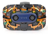
crwdns2915892:0crwdne2915892:0
Prerequisite guide to disconnect the daughterboard in the HTC Vive Pro 2 headset.
crwdns2942213:0crwdne2942213:0
-
-
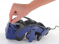
Rotate the head strap forward as far as it will go.
-
-
-
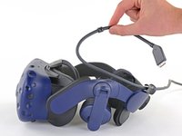
Unplug the All-In-One Cable from your headset.
-
-
-
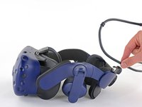
Remove the All-In-One Cable from the cable guides along the left side of the head strap.
-
-
-
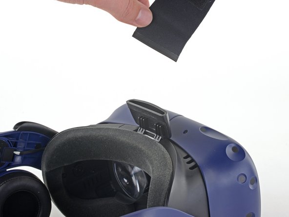
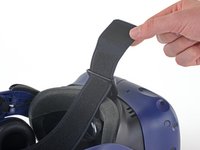
Separate the top strap from itself where the Velcro secures it.
-
-
-
Peel back the Velcro securing the rear of the top strap.
-
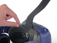
Feed the top strap out through the head strap to partially remove it.
-
-
-
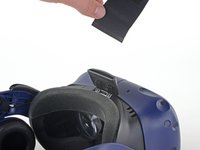
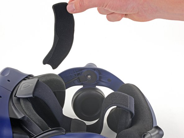
Feed the top strap through the clip near the front of headset to fully remove it.
-
-
-
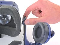
Peel off both front side foam pads to uncover the speaker wires.
-
-
-
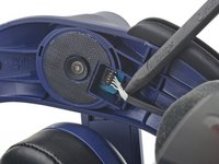
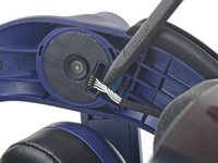
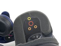
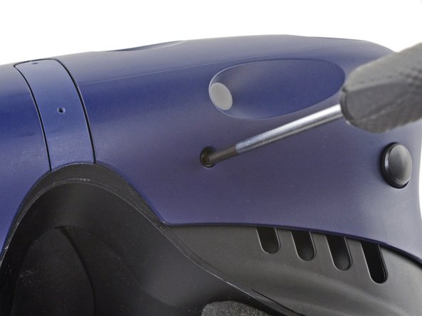
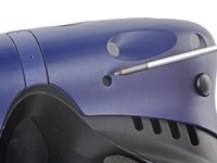
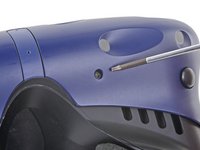
Use the point of your spudger to pry out the two rubber spacers next to the headphone screws.
-
-
-
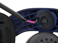
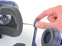
Use the point of your spudger to pry up and disconnect both the left and right headphone speaker wires.
-
-
-
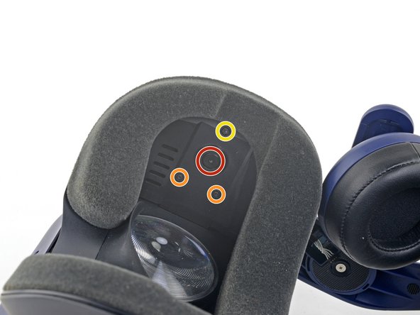
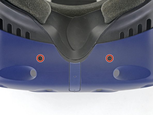
Use a T6 Torx screwdriver to remove the two 12.1 mm screws (one on each side) securing the head strap to the headset.
-
Use a T5 Torx screwdriver to remove the following screws securing the head strap to the headset:
-
Four 3.9 mm screws (two on each side)
-
Two 4.1 mm screws (one on each side)
-
-
-
Remove the two plastic spacers underneath the previously removed Torx T6 screw.
-
-
-
-
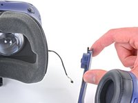
Thread the headphone speaker wires out through both ends of the head strap.
-
-
-
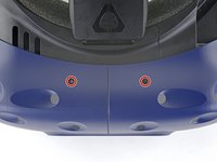
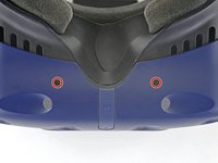
Use a T6 Torx screwdriver to remove the four 3.9 mm screws (two on top, two on bottom) securing the outer shell to the headset.
-
-
-
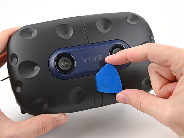
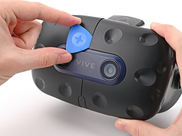
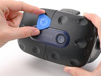
Insert an opening pick into the seam between the two halves of the outer shell.
-
Slide the opening pick through the seam to dislodge the clips securing it to the headset.
-
-
-
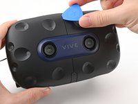
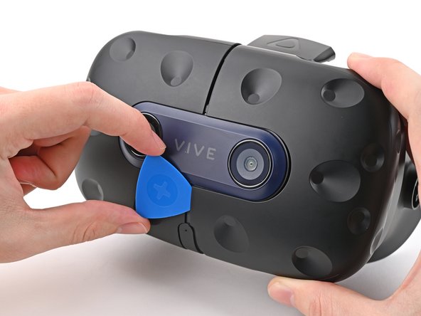
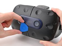
Continue sliding the opening pick through each seam until all clips have been dislodged.
-
-
-
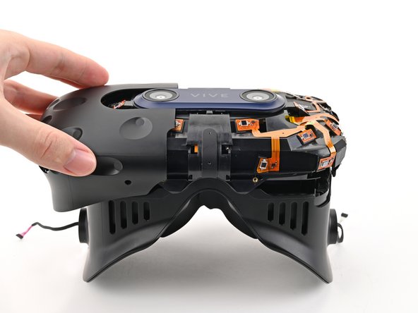
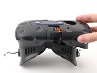
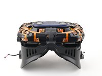
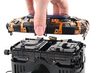
Carefully slide each half of the outer shell off of the sensor array.
-
-
-
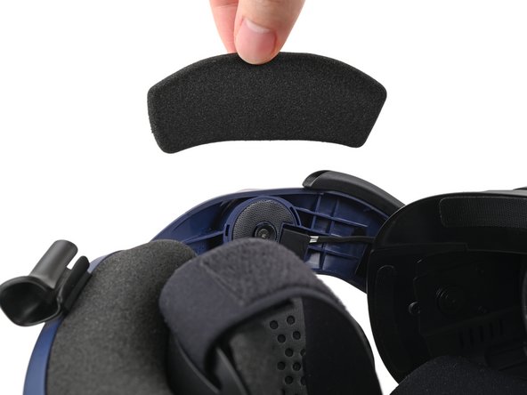
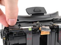
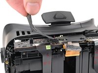
Use your fingers to gently peel the face rest cushion off of the headset.
-
-
-
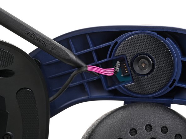
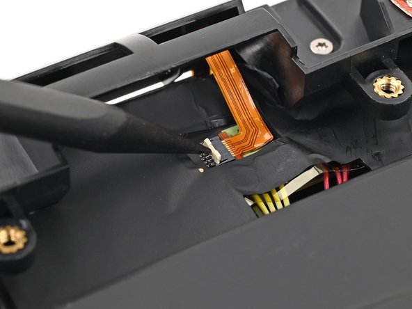
Use the point of your spudger, or a clean fingernail, to flip up the locking tab on the microphone ZIF connector on the daughterboard.
-
-
-
Use tweezers, or your fingers, to pull the microphone cable straight out of its socket.
-
-
-
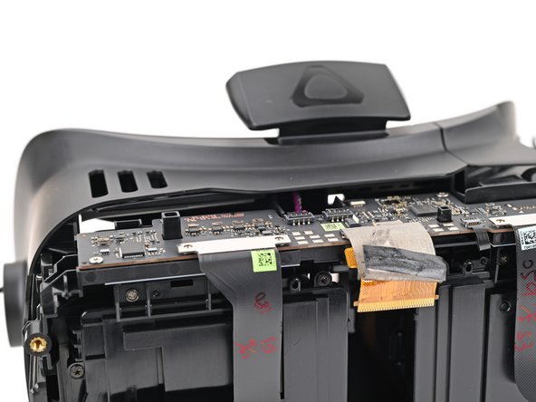
Use tweezers, or your fingers, to peel the conductive fabric off the sensor array ZIF connector on the motherboard.
-
-
-
Use your spudger, or a clean fingernail, to flip up the locking tab on the sensor array ZIF connector.
-
-
-
Use your fingers to grip the left and right sides of the sensor array cable and pull it straight out of its socket.
-
-
-
Use a T5 Torx screwdriver to remove the four 3.0 mm‑long screws securing the top of the sensor array.
-
-
-
Use a T6 Torx screwdriver to remove the four 3.8 mm‑long screws securing the front of the sensor array.
-
-
-
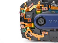
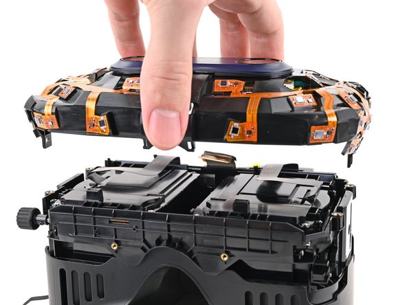
Lift the sensor array straight off the lens assembly and remove it, making sure you thread the cable through its slot.
-
-
-
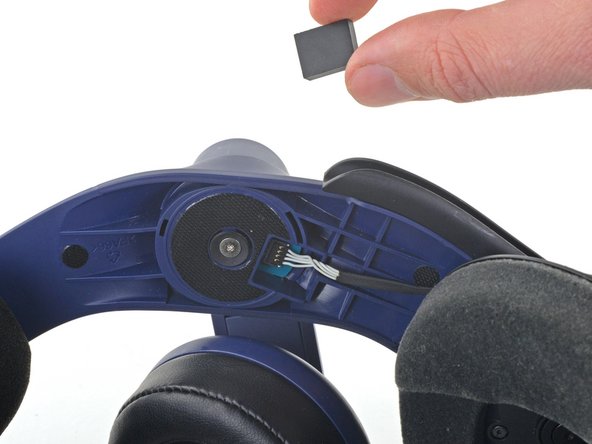
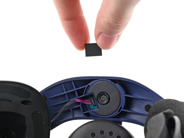
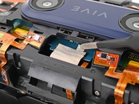
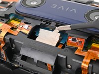
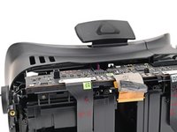
Use your fingers to peel up the thermal pad covering the daughterboard.
-
-
-
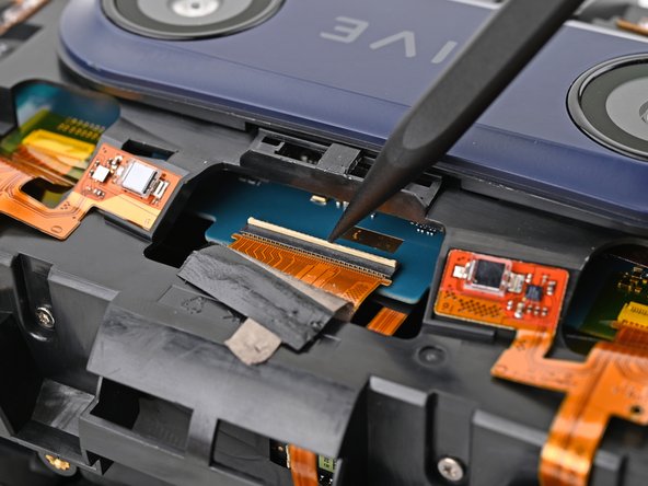
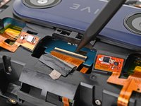
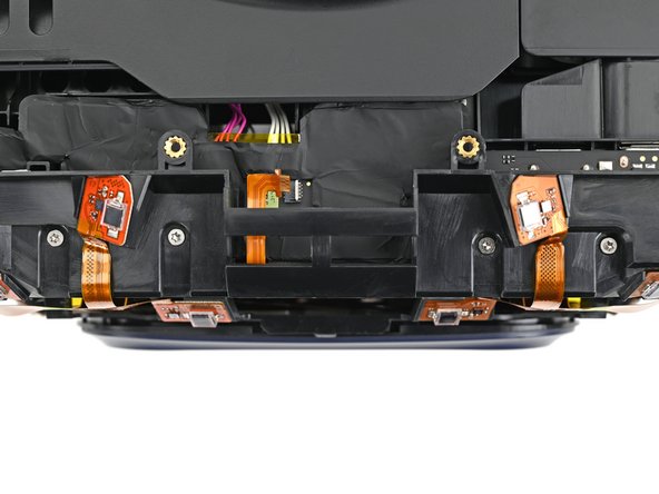
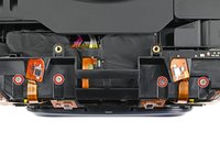
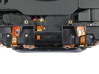
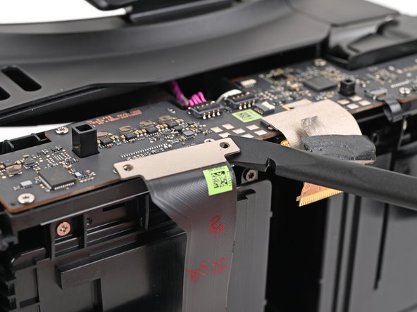
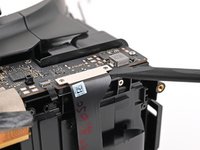
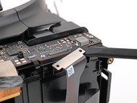
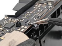
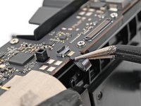
Insert the flat end of a spudger under a corner of the lens assembly press connector.
-
Twist the spudger to lift the press connector up and disconnect it.
-
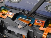
Repeat the same process to disconnect the other lens assembly press connector.
-
-
-
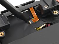
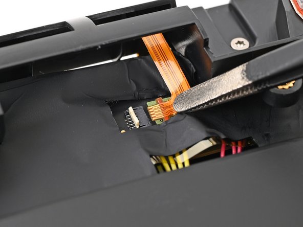
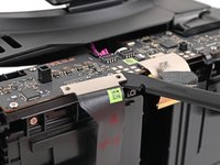
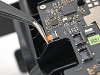
Use the point of a spudger to lift up the locking tab on the IPD sensor ZIF connector.
-
-
-
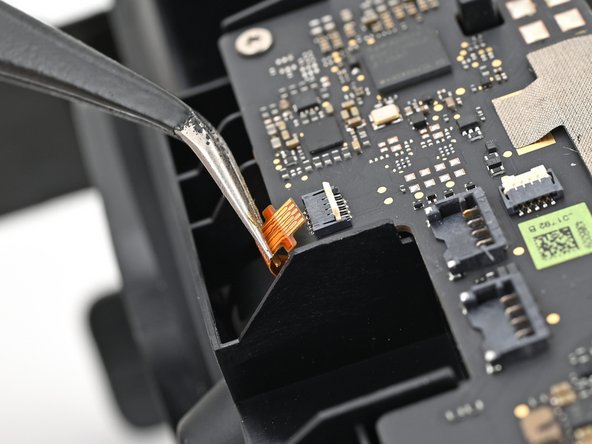
Use tweezers, or your fingers, to pull the IPD sensor cable straight out of its socket.
-
-
-
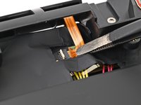
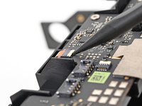
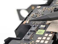
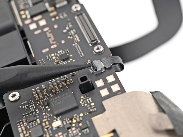
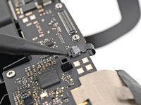
Use the point of a spudger to lift up the locking tab on the proximity sensor ZIF connector.
-
-
-
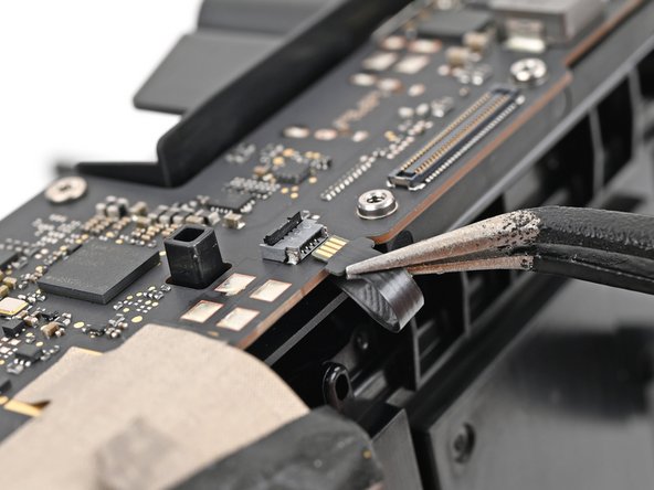
Use tweezers, or your fingers, to pull the proximity sensor cable straight out of its socket.
-


To reassemble your device, follow these instructions in reverse order.
To reassemble your device, follow these instructions in reverse order.

