crwdns2915892:0crwdne2915892:0
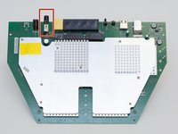
The power switch is the black button on the back of the router. If it is not pressing and appears to be broken, this guide will walk you through on the replacement of this switch.
crwdns2942213:0crwdne2942213:0
-
-
Peel off the four rubber rectangular feet with your fingers.
-
-
-
Unscrew the 5mm screws in each corner using the Phillips #1 screwdriver.
-
-
-
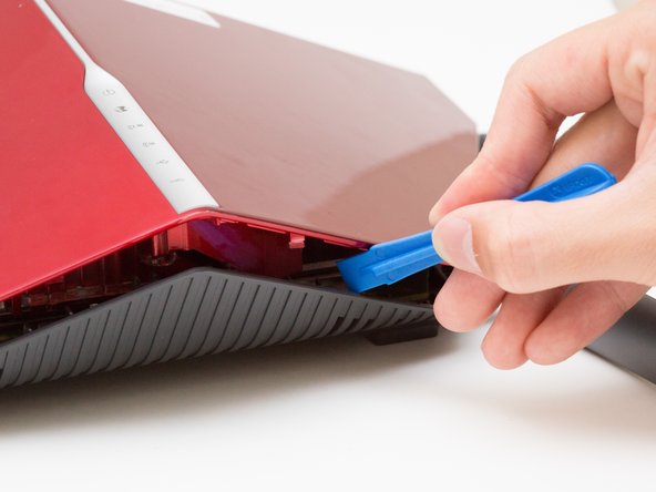
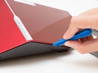
Wedge the opening tool between the red top panel and the gray bottom panel.
-
Twist the opening tool to separate the panels. Work your way around the case until both of the panels are separated.
-
-
-
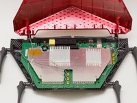
Orient the router so the narrow end of the router faces you and the ports face away from you.
-
The six, hot-glued antenna connections are in the middle and at the top right of the motherboard.
-
-
-
crwdns2935267:0crwdne2935267:0Heavy-Duty Spudger$4.99
-
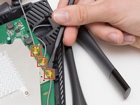
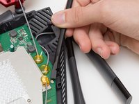
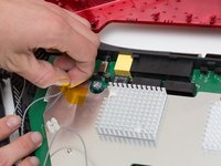
Pry off the antenna connectors using a heavy-duty spudger.
-
-
-
Continue to pry off the last three antenna connections on the upper right portion of the motherboard.
-
-
-
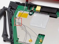
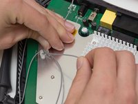
Open the plastic bracket enclosing the three antenna wires and pull the wires out with your hands.
-
-
-
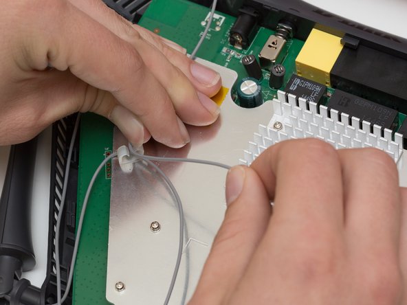
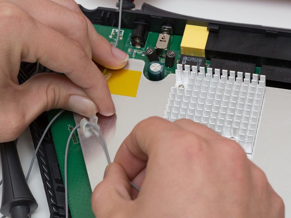
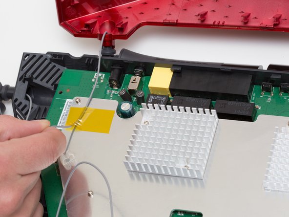
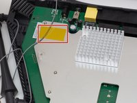
Pull the yellow tape off of the motherboard to release the final antenna wire.
-
-
-
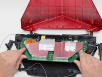
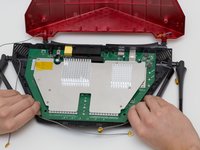
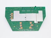
Pull the the motherboard away from the case to remove it. Start on the side closest to you, and pull up and out.
-
-
-
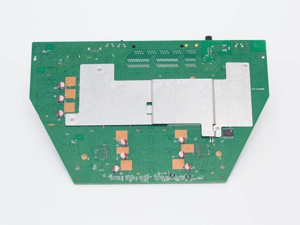
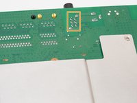
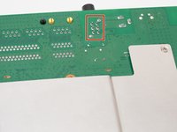
Locate the power switch on the top left of the motherboard.
-
Turn the motherboard upside down.
-
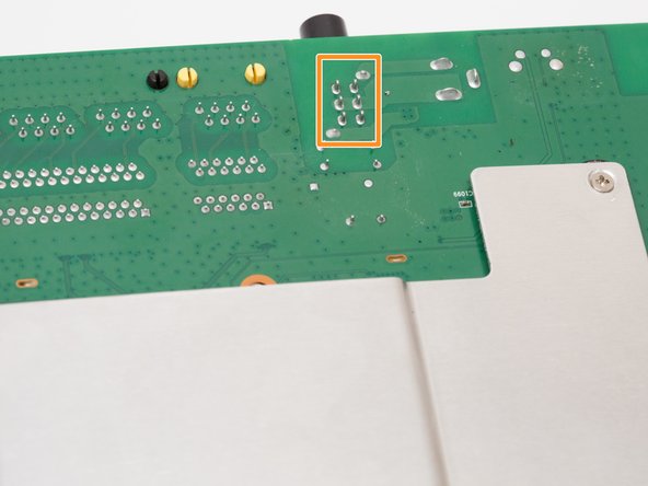
Locate the 6 solder joints that connect the power switch to the motherboard. They are arranged in 2 columns of 3.
-
-
crwdns2935267:0crwdne2935267:0Desoldering Pump$3.99
-
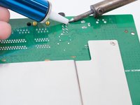
Using a soldering iron and desoldering pump, desolder the power switch from the board.
-


To reassemble your device, follow these instructions in reverse order.
To reassemble your device, follow these instructions in reverse order.
crwdns2915084:0crwdne2915084:0

Cal Poly, Team 10-7, Livingston Fall 2016 crwdns2935289:0Cal Poly, Team 10-7, Livingston Fall 2016crwdne2935289:0
CPSU-LIVINGSTON-F16S10G7
crwdns2931471:04crwdne2931471:0
crwdns2935297:012crwdne2935297:0