crwdns2933423:0crwdne2933423:0

Connecting Cables to the Motherboard

crwdns2942213:0crwdne2942213:0

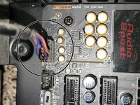
  1. Connecting Cables to the Motherboard, Connecting Cables to the Motherboard: crwdns2935265:01crwdnd2935265:01crwdnd2935265:02crwdne2935265:0 Connecting Cables to the Motherboard, Connecting Cables to the Motherboard: crwdns2935265:01crwdnd2935265:02crwdnd2935265:02crwdne2935265:0
    • Red- Optional ATX Connector

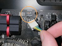
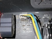
    • Orange- CPU Fan 1

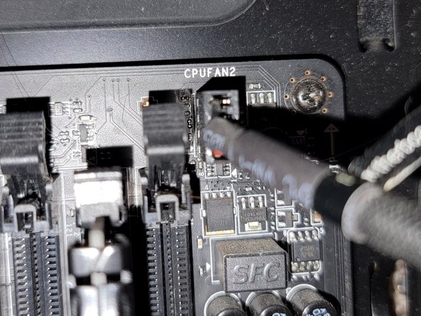
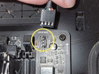
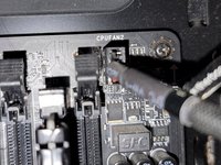
    • Yellow- CPU Fan 2

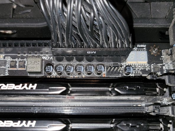
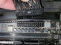
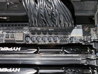
    • Green- Main ATX Connectors

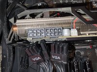
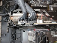
    • Light Blue- GPU

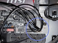
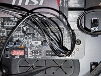
    • Blue- Panel Connectors

    • Pink- USB Connectors

    • Black- HD Audio

  2. Connecting Cables to the Motherboard, Optional ATX Connector: crwdns2935265:02crwdnd2935265:01crwdnd2935265:02crwdne2935265:0 Connecting Cables to the Motherboard, Optional ATX Connector: crwdns2935265:02crwdnd2935265:02crwdnd2935265:02crwdne2935265:0
    • Connect the two separate six-pin segments to six pins each on the 12-pin PCIE port.

  3. Connecting Cables to the Motherboard, CPU Fan 1: crwdns2935265:03crwdnd2935265:01crwdnd2935265:02crwdne2935265:0 Connecting Cables to the Motherboard, CPU Fan 1: crwdns2935265:03crwdnd2935265:02crwdnd2935265:02crwdne2935265:0
    • Connect the four pin segment to the four pin PCEI connector labeled "CPUFAN1."

  4. Connecting Cables to the Motherboard, CPU Fan 2: crwdns2935265:04crwdnd2935265:01crwdnd2935265:02crwdne2935265:0 Connecting Cables to the Motherboard, CPU Fan 2: crwdns2935265:04crwdnd2935265:02crwdnd2935265:02crwdne2935265:0
    • Connect the four pin segment to the four pin PCIE port labeled "CPUFAN2."

  5. Connecting Cables to the Motherboard, Main ATX Connector: crwdns2935265:05crwdnd2935265:01crwdnd2935265:02crwdne2935265:0 Connecting Cables to the Motherboard, Main ATX Connector: crwdns2935265:05crwdnd2935265:02crwdnd2935265:02crwdne2935265:0
    • Connect the 24 pin segment to the 24 pin PCIE port.

  6. Connecting Cables to the Motherboard, GPU: crwdns2935265:06crwdnd2935265:01crwdnd2935265:02crwdne2935265:0 Connecting Cables to the Motherboard, GPU: crwdns2935265:06crwdnd2935265:02crwdnd2935265:02crwdne2935265:0
    • Connect both of the separate eight pin segments to each of the eight pin PCIE ports on the graphics card.

  7. Connecting Cables to the Motherboard, Panel Connectors (Part 1): crwdns2935265:07crwdnd2935265:01crwdnd2935265:03crwdne2935265:0 Connecting Cables to the Motherboard, Panel Connectors (Part 1): crwdns2935265:07crwdnd2935265:02crwdnd2935265:03crwdne2935265:0 Connecting Cables to the Motherboard, Panel Connectors (Part 1): crwdns2935265:07crwdnd2935265:03crwdnd2935265:03crwdne2935265:0
    • This PCIE port consists of eight pins, two rows of four.

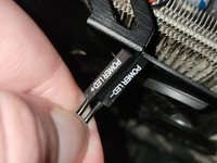
    • Connect the "Power LED+" pin to the pin at the top right corner.

    • Connect the "Power LED-" segment to the pin next to the "Power LED+" segment in the top row.

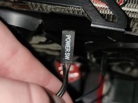
    • Connect the "Power SW" segment to the two pins on the left side of the top row of pins.

  8. Connecting Cables to the Motherboard, Panel Connectors (Part 2): crwdns2935265:08crwdnd2935265:01crwdnd2935265:03crwdne2935265:0 Connecting Cables to the Motherboard, Panel Connectors (Part 2): crwdns2935265:08crwdnd2935265:02crwdnd2935265:03crwdne2935265:0 Connecting Cables to the Motherboard, Panel Connectors (Part 2): crwdns2935265:08crwdnd2935265:03crwdnd2935265:03crwdne2935265:0
    • Connect the "HDD LED" segment to the two pins on the right side of the bottom row of pins.

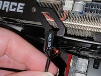
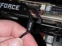
    • Connect the "Reset SW" segment to the two pins on the left side of the bottom row of pins.

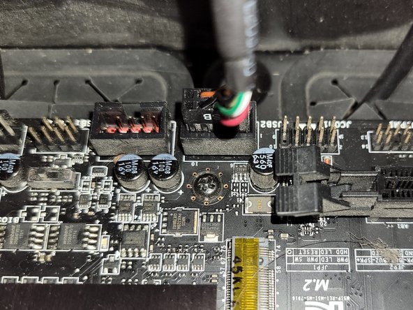
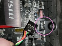
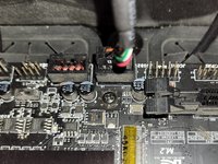
  9. Connecting Cables to the Motherboard, USB Connector: crwdns2935265:09crwdnd2935265:01crwdnd2935265:02crwdne2935265:0 Connecting Cables to the Motherboard, USB Connector: crwdns2935265:09crwdnd2935265:02crwdnd2935265:02crwdne2935265:0
    • Connect the nine pin segment to the nine pin PCIE port.

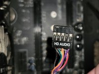
  10. Connecting Cables to the Motherboard, HD Audio: crwdns2935265:010crwdnd2935265:01crwdnd2935265:02crwdne2935265:0 Connecting Cables to the Motherboard, HD Audio: crwdns2935265:010crwdnd2935265:02crwdnd2935265:02crwdne2935265:0
    • Connect the nine pin segment to the nine pin PCIE port.

crwdns2915888:0crwdne2915888:0

To disconnect the cable ties, follow these directions in reverse order.

crwdns2935229:02crwdne2935229:0

Grace Parsekian

crwdns2935283:012/05/23crwdne2935283:0

241 crwdns2915208:0crwdne2915208:0

crwdns2935295:0crwdne2935295:0

crwdns2947410:01crwdne2947410:0

Rest comment brancher un processeur. Merci comme-me.

Kader Lahcene - crwdns2934203:0crwdne2934203:0

crwdns2917038:0crwdne2917038:0

crwdns2936625:0crwdne2936625:0:

crwdns2936751:024crwdne2936751:0 27

crwdns2936753:07crwdne2936753:0 272

crwdns2936753:030crwdne2936753:0 1,098

crwdns2942667:0crwdne2942667:0 10,220