-
-
Remove the shutter speed dial.
-
Set the shutter speed to 1/30 as it conveniently exposes the set screws. However, one can still infer the correct position by turning the dial to one end (30) or by the dents for the screws.
-
Unscrew the two set screws. No need to extract them as they are easy to lose.
-
Pull up the dial.
-
Set the flash sync dial to "0" for bookeeping. One may still infer the dial position by fitting the dial (on the camera body) between the lever notch (on the top cover).
-
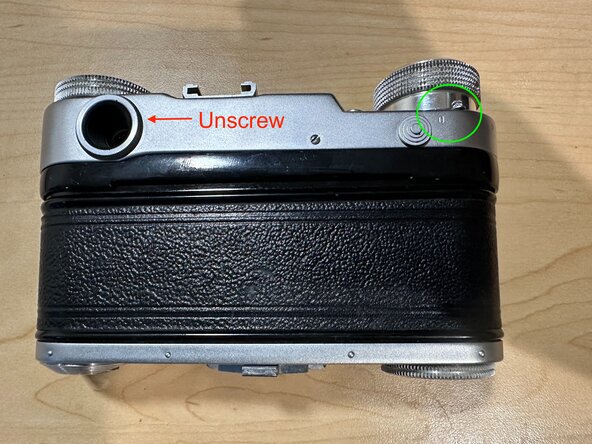
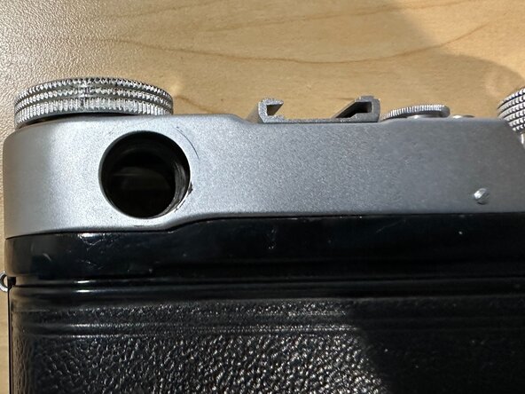
Unscrew the viewfinder eyepiece.
-
Pull up the rewind knob to the "rewind" configuration.
-
Release as much tension from the motor as possible by firing the shutter until the camera no longer autorewinds.
-
-
-
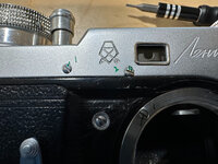
Remove the 4 set screws around the top cover.
-
There are 4 screw: front, back, left, and right
-
Screw #2 does not need to be removed. It covers the RF calibration access port.
-
Gently lift up the top cover.
-
Relieving as much tension in the motor spring as possible will make pulling up the cover much easier.
-
-
-
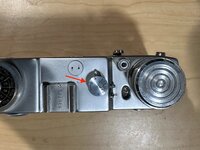
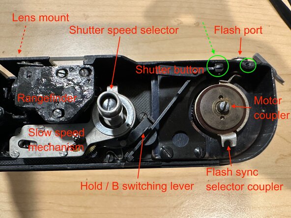
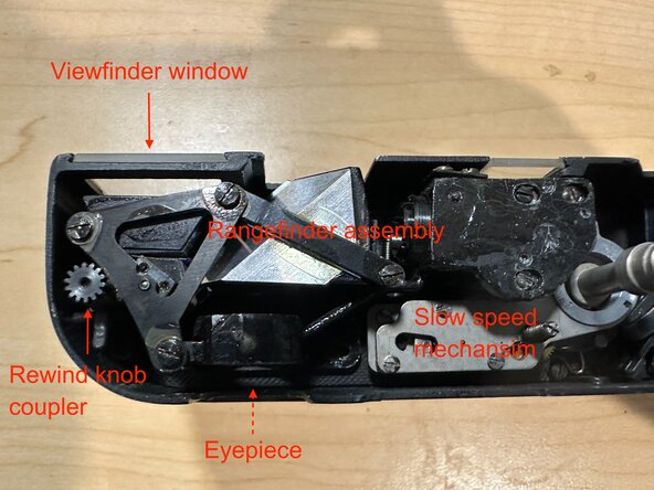
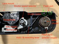
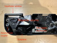
With the top cover off, take a close look at the mechanism.
-
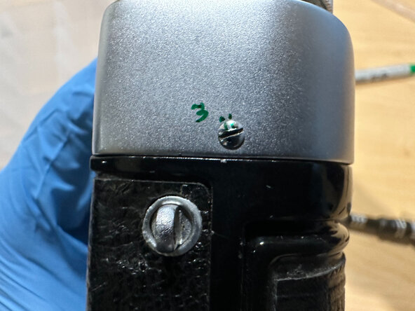
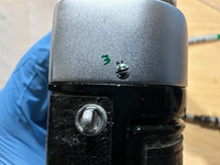
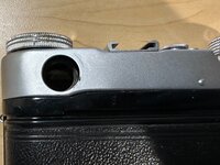
Unscrew and remove the shutter button and flash port.
-
The flash port screw is visible in the picture.
-
The shutter button screw is not pictured. It is on the front side of the camera as indicated by the green dashed arrow.
-
-
-
-
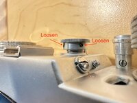
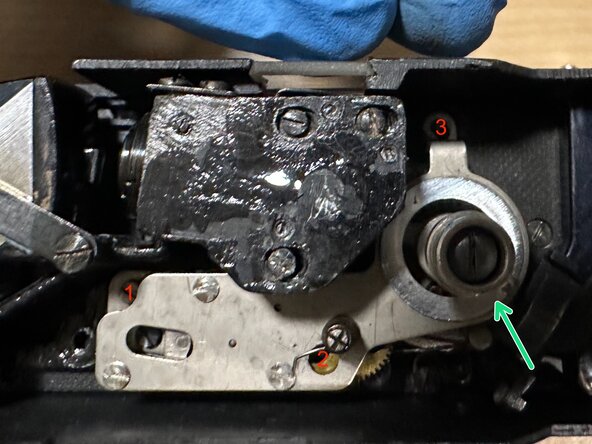
Remove the 3 screws fastening the slow speed mechansim.
-
Screw #2 is hidden under a gear. To access it, rotate the gear so the hole aligns with the screw.
-
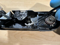
Remove the slow speed mechanism
-
Similar to all Soviet single-dial slow speed mechanisms (without separate escapement), it will release tension and buzz briefly upon removal.
-
During reassembly, the mechanism has to be pre-tensioned and installed quickly so the cam catches on before losing all tension.
-
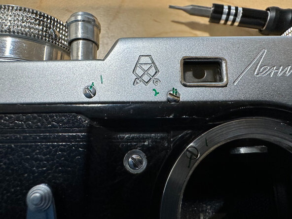
Remove the speed selector by undoing the green screw.
-
-
-
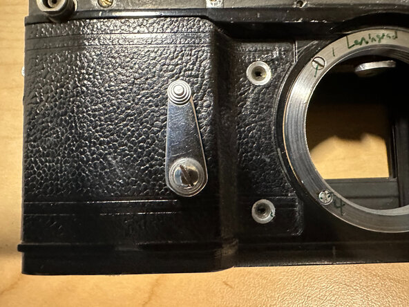
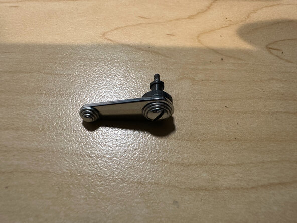
Unscrew the flathead screw on the self timer lever.
-
Remove it.
-
Note that the camera was jammed when I took the picture. Normally the shutter curtain should be closed at this stage
-
-
-
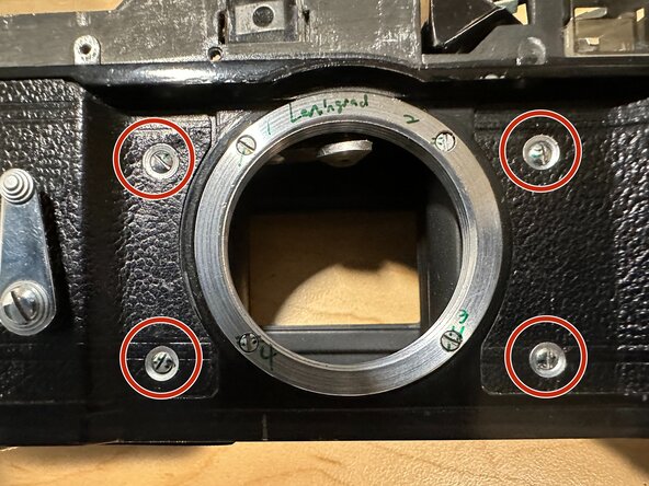
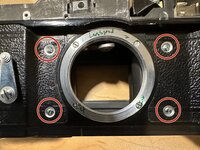
Remove the 4 front screws circled in red. Beware of the cone washers between the leatherette and the screws. They could fall out.
-
Early versions of Leningrad may only have 2 screws
-
Do not remove the screws on the mount (marked 1~4). There is no need. Reassembling the lens mount requires collimating.
-
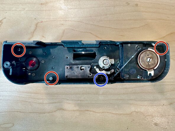
Remove the 4 top screws.
-
Order the screws carefully. They may not be the same length.
-
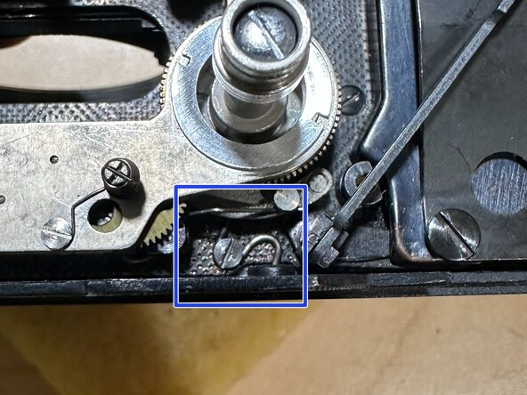
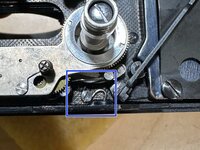
Pay special attention to how the S-shaped spring is arranged (blue circle and rectangle). It is crucial for absorbing the shock from the motor winder.
-
The pictured configuration shows the correct assembly. The left side of the spring stops the winding action. The right side holds the spring against the chassis. It is under a lot of tension and reassembling it is tricky.
-
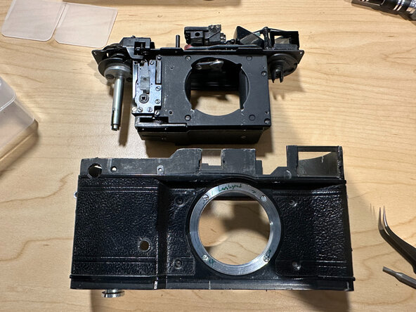
Pull off the chassis.
-
-
-
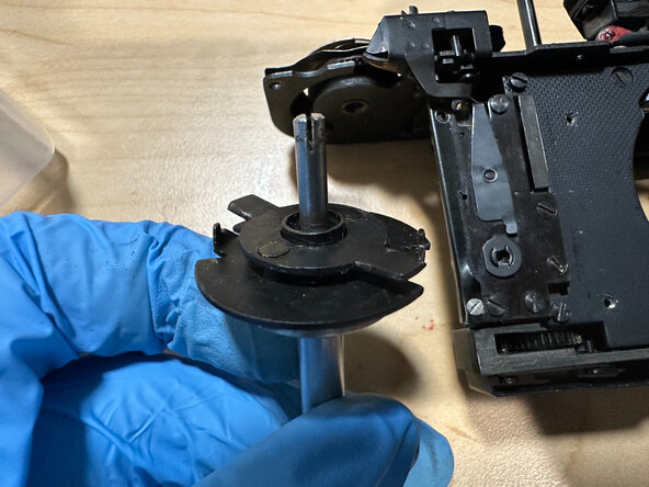
With the chassis off, you may now take out the winder spool.
-
Study how the motor winder mechanism works.
-
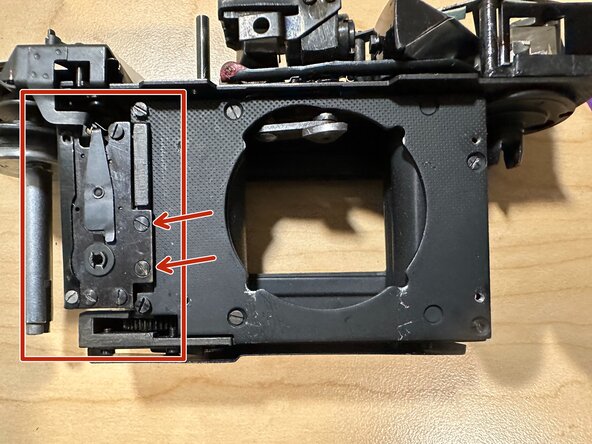
The self timer mechanism is now accessible. If needed, remove the two screws securing it (red arrow) to service it.
-


To reassemble your device, follow these instructions in reverse order.
To reassemble your device, follow these instructions in reverse order.
