crwdns2942213:0crwdne2942213:0
-
crwdns2935201:0crwdne2935201:0 crwdns2935203:0crwdne2935203:0
-
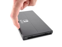
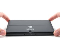
Press and hold down the small round button on the back of the Joy Con controller.
-
While you hold down the button, slide the controller upward.
-
-
crwdns2935201:0crwdne2935201:0 crwdns2935203:0crwdne2935203:0
-
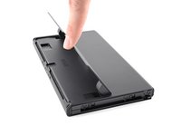
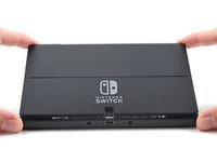
Continue sliding the Joy Con upward until it's completely removed from the console.
-
-
crwdns2935201:0crwdne2935201:0 crwdns2935203:0crwdne2935203:0
-
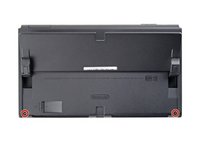
Use a Phillips driver, or a JIS driver, to remove the 2 mm-long screw securing the top of the rear case to the frame.
-
-
crwdns2935201:0crwdne2935201:0 crwdns2935203:0crwdne2935203:0
-
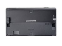
Use a Phillips driver to remove the two 2 mm-long screws securing the bottom of the rear case to the frame.
-
-
crwdns2935201:0crwdne2935201:0 crwdns2935203:0crwdne2935203:0
-
Use a Phillips driver to remove the 3.8 mm screw securing the right Joy-Con sensor rail to the rear case.
-
-
crwdns2935201:0crwdne2935201:0 crwdns2935203:0crwdne2935203:0
-
Use a Phillips driver to remove the 3.8 mm screw securing the left Joy-Con sensor rail to the rear case.
-
-
crwdns2935201:0crwdne2935201:0 crwdns2935203:0crwdne2935203:0
-
Use your finger to flip up the kickstand on the back of the device.
-
-
crwdns2935201:0crwdne2935201:0 crwdns2935203:0crwdne2935203:0
-
Use a Y00 screwdriver to remove the two 4.3 mm screws securing the rear case to the frame.
-
-
crwdns2935201:0crwdne2935201:0 crwdns2935203:0crwdne2935203:0
-
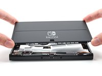
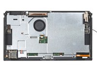
Lift the rear case up from the top of the device and remove it.
-
-
crwdns2935201:0crwdne2935201:0 crwdns2935203:0crwdne2935203:0
-
Use the flat end of a spudger to separate a corner of the tape from the shield plate.
-
-
crwdns2935201:0crwdne2935201:0 crwdns2935203:0crwdne2935203:0
crwdns2935267:0crwdne2935267:0Tweezers$4.99-
Use tweezers, or your fingers, to peel back and remove the tape.
-
-
crwdns2935201:0crwdne2935201:0 crwdns2935203:0crwdne2935203:0
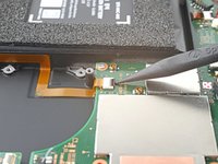
-
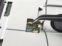
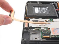
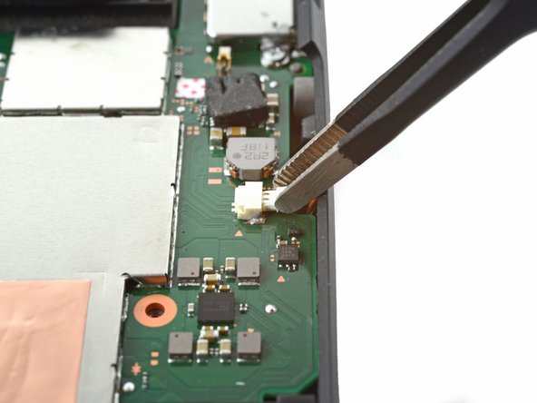
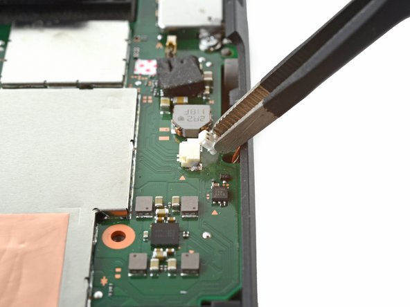
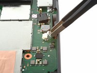
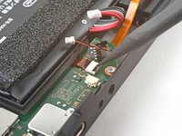
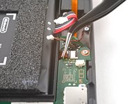
Use tweezers, or your fingers, to pull up and disconnect the primary Wi-Fi antenna's coaxial cable.
-
-
crwdns2935201:0crwdne2935201:0 crwdns2935203:0crwdne2935203:0
-
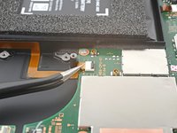
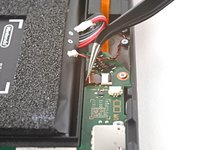
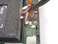
Use tweezers, or your fingers, to reroute the primary antenna's coaxial cable out of its slots in the shield plate.
-
-
crwdns2935201:0crwdne2935201:0 crwdns2935203:0crwdne2935203:0
-
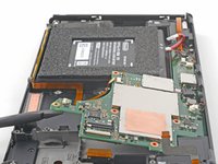
Use a Phillips driver to remove the two 4.4 mm screws securing the primary Wi-Fi antenna to the shield plate.
-
-
crwdns2935201:0crwdne2935201:0 crwdns2935203:0crwdne2935203:0
-
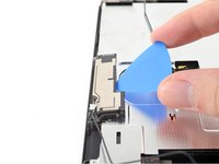
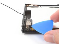
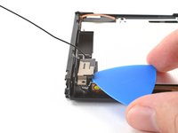
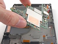
Insert an opening pick between the primary Wi-Fi antenna and the shield plate.
-
Pry up with the pick to separate the primary Wi-Fi antenna from the shield plate.
-
-
-
crwdns2935201:0crwdne2935201:0 crwdns2935203:0crwdne2935203:0
-
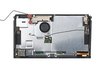
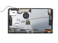
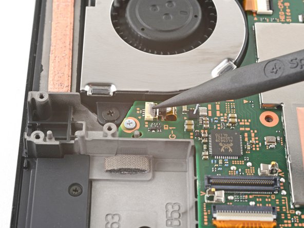
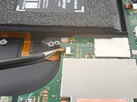
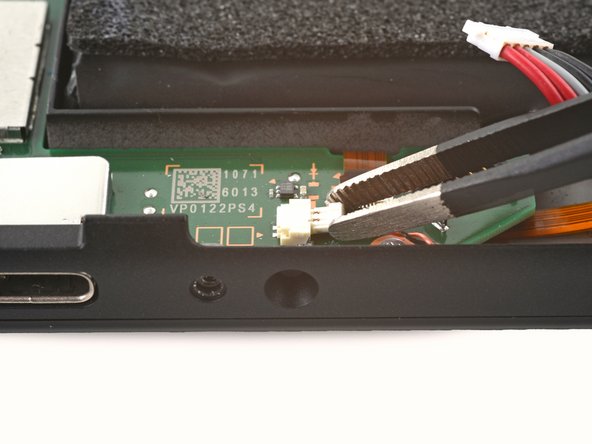
Use tweezers, or your fingers, to pull up and disconnect the secondary Wi-Fi antenna's coaxial cable.
-
-
crwdns2935201:0crwdne2935201:0 crwdns2935203:0crwdne2935203:0
-
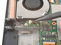
Use the point of a spudger to reroute the secondary Wi-Fi antenna's coaxial cable from its slot in the frame.
-
-
crwdns2935201:0crwdne2935201:0 crwdns2935203:0crwdne2935203:0
-
Use a Phillips driver to remove the 4.4 mm screw securing the secondary Wi-Fi antenna to the shield plate.
-
-
crwdns2935201:0crwdne2935201:0 crwdns2935203:0crwdne2935203:0
-
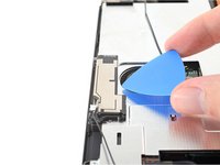
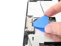
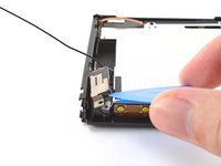
Insert an opening pick between the secondary Wi-Fi antenna and the shield plate.
-
Pry up with the pick to separate the secondary Wi-Fi antenna from the shield plate.
-
-
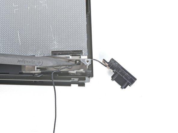
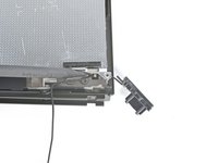
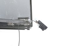
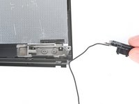
crwdns2935201:0crwdne2935201:0 crwdns2935203:0crwdne2935203:0
-
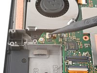
Use the point of a spudger to reroute the secondary Wi-Fi antenna's coaxial cable out of its slot in the frame.
-
Remove the secondary Wi-Fi antenna.
-
-
crwdns2935201:0crwdne2935201:0 crwdns2935203:0crwdne2935203:0
-
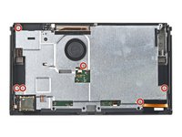
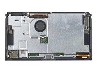
Use a Phillips driver to remove the six 4.4 mm screws securing the shield plate to the frame.
-
-
crwdns2935201:0crwdne2935201:0 crwdns2935203:0crwdne2935203:0
-
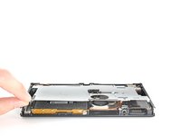
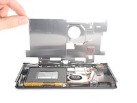
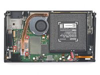
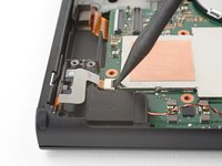
Use your fingers to lift the top of the shield plate up and away from the frame.
-
Remove the shield plate.
-
-
crwdns2935201:0crwdne2935201:0 crwdns2935203:0crwdne2935203:0
-
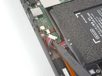
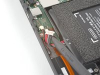
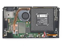
Use the point of a spudger to pry up and disconnect the battery.
-
-
crwdns2935201:0crwdne2935201:0 crwdns2935203:0crwdne2935203:0
crwdns2935267:0crwdne2935267:0Tweezers$4.99-
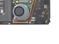
Use tweezers, or your fingers, to remove the piece of tape obscuring the daughterboard's screw.
-
-
crwdns2935201:0crwdne2935201:0 crwdns2935203:0crwdne2935203:0
-
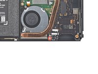
Use a Phillips driver to remove the 4 mm screw securing the daughterboard to the frame.
-
-
crwdns2935201:0crwdne2935201:0 crwdns2935203:0crwdne2935203:0
-
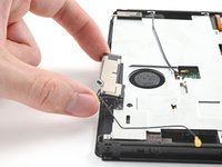
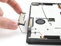
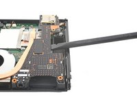
Insert a spudger between the edge of the daughterboard and the motherboard.
-
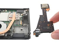
Pry up with the spudger to disconnect the press connector and separate the daughterboard from the frame.
-
Remove the daughterboard.
-
-
crwdns2935201:0crwdne2935201:0 crwdns2935203:0crwdne2935203:0
-
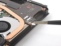
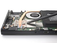
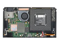
Use a Phillips driver to remove the three 3 mm screws securing the heat sink to the motherboard.
-
-
crwdns2935201:0crwdne2935201:0 crwdns2935203:0crwdne2935203:0
-
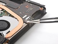
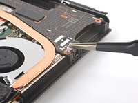
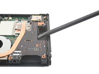
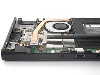
Insert a spudger between the heat sink's bracket and the motherboard.
-
Pry up with the spudger to separate the heat sink from the motherboard.
-
-
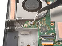
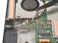
crwdns2935201:0crwdne2935201:0 crwdns2935203:0crwdne2935203:0
-
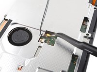
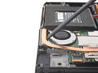
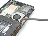
Insert a spudger in the gap between the fan and the heat sink.
-
Pry up with the spudger to separate the heat sink from the adhesive beneath it.
-
Remove the heat sink.
-
-
crwdns2935201:0crwdne2935201:0 crwdns2935203:0crwdne2935203:0
-
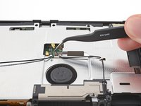
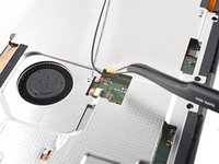
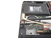
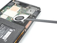
Use the tip of a spudger, an opening tool, or your fingernail to flip up the small, hinged locking flap on the fan cable's ZIF connector.
-
-
crwdns2935201:0crwdne2935201:0 crwdns2935203:0crwdne2935203:0
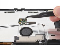
crwdns2935267:0crwdne2935267:0Tweezers$4.99-
Use a pair of tweezers to pull the fan cable straight out of its connector on the motherboard.
-
-
crwdns2935201:0crwdne2935201:0 crwdns2935203:0crwdne2935203:0
-
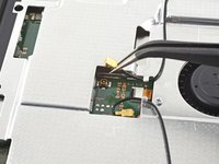
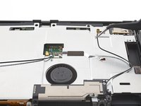
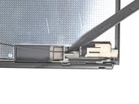
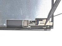
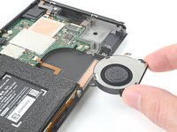
Use a Phillips driver to remove the three 3 mm screws securing the fan to the frame.
-
-
crwdns2935201:0crwdne2935201:0 crwdns2935203:0crwdne2935203:0
-
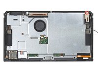
Use a spudger to lift the fan out straight out of the frame.
-
Remove the fan.
-
-
crwdns2935201:0crwdne2935201:0 crwdns2935203:0crwdne2935203:0
-
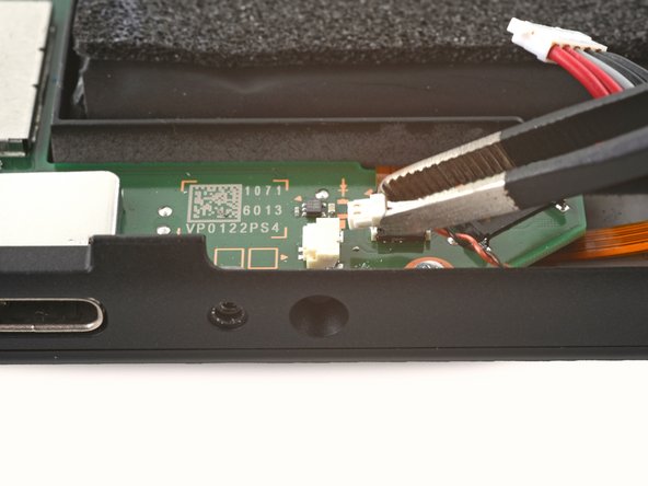
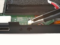
Use an opening tool, spudger, or your fingernail to flip up the small, hinged locking flap on the power button board's ZIF connector.
-
-
crwdns2935201:0crwdne2935201:0 crwdns2935203:0crwdne2935203:0
crwdns2935267:0crwdne2935267:0Tweezers$4.99-
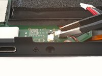
Use a pair of tweezers to pull the power button board cable straight out of its connector on the motherboard.
-
-
crwdns2935201:0crwdne2935201:0 crwdns2935203:0crwdne2935203:0
-
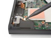
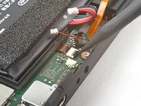
Use an opening tool, spudger, or your fingernail to flip up the small, hinged locking flap on the right Joy-Con sensor rail's ZIF connector.
-
-
crwdns2935201:0crwdne2935201:0 crwdns2935203:0crwdne2935203:0
-
Use a pair of tweezers to pull the right Joy-Con sensor rail's cable straight out of its connector on the motherboard.
-
-
crwdns2935201:0crwdne2935201:0 crwdns2935203:0crwdne2935203:0
-
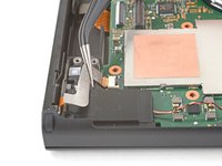
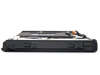
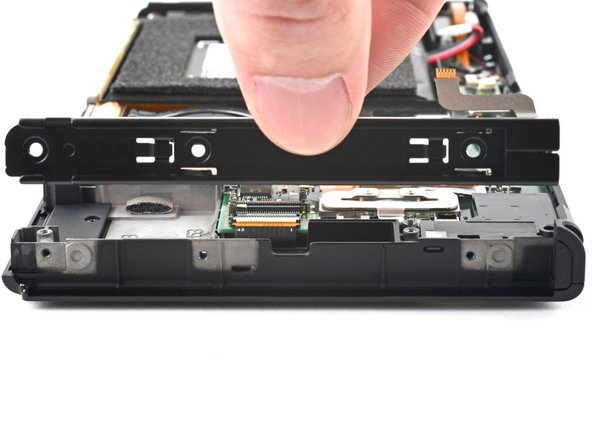
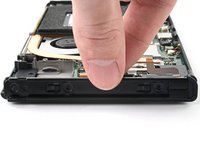
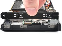
Use a Phillips driver to remove the two 3.8 mm screws securing the left Joy-Con sensor rail to the frame.
-
-
crwdns2935201:0crwdne2935201:0 crwdns2935203:0crwdne2935203:0
-
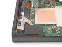
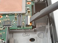
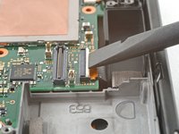
Use an opening tool, spudger, or your fingernail to flip up the hinged locking flap on the display's ZIF connector.
-
-
crwdns2935201:0crwdne2935201:0 crwdns2935203:0crwdne2935203:0
-
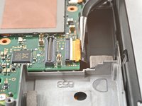
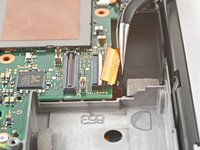
Use a pair of tweezers to pull the display cable straight out of its connector on the motherboard.
-
-
crwdns2935201:0crwdne2935201:0 crwdns2935203:0crwdne2935203:0
-
Use tweezers, or your fingers, to pull the left speaker's JST connector out of its socket.
-
-
crwdns2935201:0crwdne2935201:0 crwdns2935203:0crwdne2935203:0
-
Use tweezers, or your fingers, to pull the right speaker's JST connector out of its socket.
-
-
crwdns2935201:0crwdne2935201:0 crwdns2935203:0crwdne2935203:0
-
Use an opening tool, spudger, or your fingernail to flip up the small, hinged locking flap on the right Joy-Con sensor rail's ZIF connector.
-
-
crwdns2935201:0crwdne2935201:0 crwdns2935203:0crwdne2935203:0
-
Use a pair of tweezers to pull the right Joy-Con sensor rail's cable straight out of its connector on the motherboard.
-
-
crwdns2935201:0crwdne2935201:0 crwdns2935203:0crwdne2935203:0
-
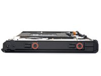
Use a Phillips driver to remove the five screws securing the midframe to the frame:
-
Three 3 mm screws
-
Two 4.4 mm screws
-
-
crwdns2935201:0crwdne2935201:0 crwdns2935203:0crwdne2935203:0
-
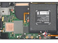
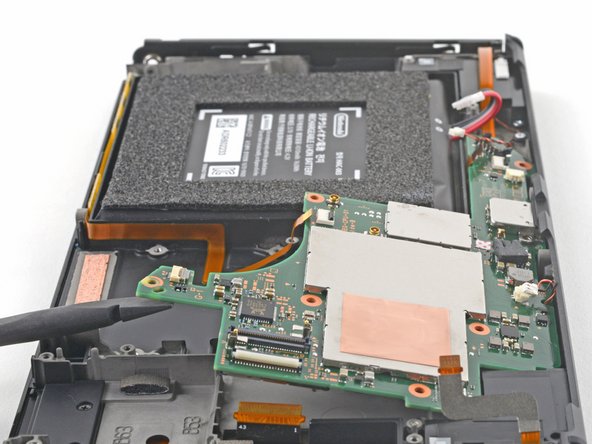
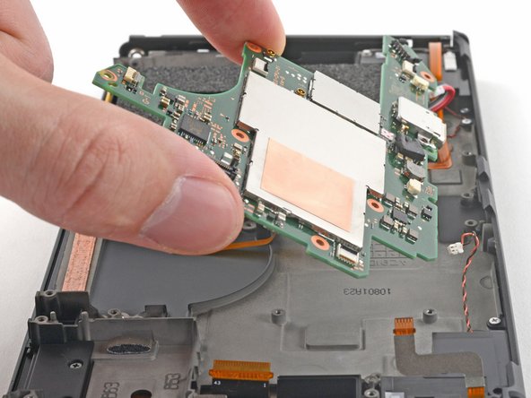
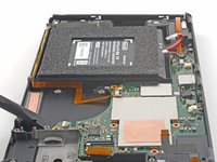
Insert a spudger between the motherboard and the frame.
-
Pry up with the spudger to separate the motherboard from the frame.
-
Remove the motherboard.
-