crwdns2915892:0crwdne2915892:0
This repair guide will explain, step-by-step the process necessary to replace the LCD Screen.
crwdns2942213:0crwdne2942213:0
-
-
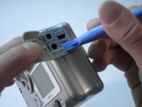
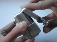
Open the battery compartment and remove the batteries.
-
Remove the two screws that are deep in the battery compartment with a Phillips #00 screwdriver.
-
-
-
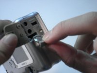
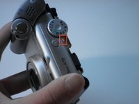
Open the CF compartment and remove the top screw with a Phillips #00 screwdriver.
-
The panel that holds the shutter button and zoom will come off.
-
-
-
Unscrew the three small screws on the bottom of the camera with a Phillips #00 screwdriver.
-
Remove the wrist strap.
-
-
-
Remove the screw in the CF compartment with a Phillips #00 screwdriver.
-
-
-
Open the rubber Digital AV Out compartment flap.
-
Pry the battery with an opening tool.
-
Carefully pull out the battery with two fingers.
-
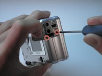
Remove the two screws that are now visible with a Phillips #00 screwdriver.
-
-
-
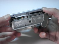
Starting from the bottom, carefully pull the casing off.
-
The casing will now pivot at the top.
-
There are three catches that hold the back casing to the body.
-
-
-
The interior of the camera should look like this.
-
-
-
Remove the two screws at the top of the battery compartment with a Phillips #00 screwdriver.
-
-
-
With your right thumb, pull back on the tab while using your left hand to pull the face of the camera away from the body.
-
-
-
After removing the front and rear panels, locate the viewfinder directly above the lens on top of the camera.
-
Three screws hold the viewfinder in place: two on the top and one on the lens side of the camera.
-
First, remove the screw in the bent corner of the viewfinder with a Phillips #00 screwdriver.
-
-
-
-
Remove the second screw directly across from the bent corner.
-
-
-
Remove the final screw directly under the left side of the viewfinder (on the lens side) with a Phillips #00 screwdriver.
-
-
-
After removing the three screws, the only thing still holding the viewfinder in place is a small plastic peg.
-
Remove the viewfinder with a firm pull directly upwards.
-
-
-
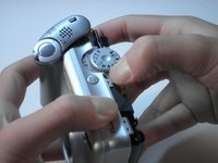
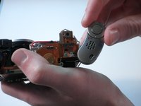
Remove the two clearly visible screws from the control dial with a Phillips #00 screwdriver.
-
Remove the dial—it should come off easily.
-
-
crwdns2935267:0crwdne2935267:0Tweezers$4.99
-
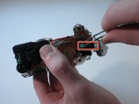
With tweezers, carefully unplug the two small wires from the green plug.
-
Carefully replace the broken speaker/shutter panel with a new one.
-
-
-
The removed panel should look like this.
-
-
-
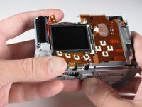
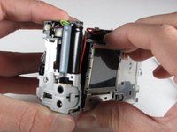
Using a Phillips #00 screwdriver, remove the one visible screw that attaches the flex assembly to the back of the camera.
-
-
-
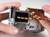
Starting with the bottom-left corner (below the screen), lift the flex assembly away from the camera chassis.
-
-
-
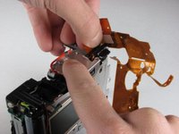
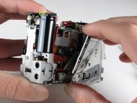
Use your finger to release the small metal tab that attaches the flex assembly to the upper-right corner of the camera.
-
-
-
Disconnect the black connector by lifting it up.
-
-
-
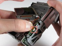
Gently pull the rest of the flex assembly away from the camera body until you reach the last connector.
-
-
-
Hold the flex assembly gently but firmly, and pull it out of the connection with two fingers.
-
-
-
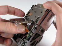
Remove the two screws from the bottom of the camera with a Phillips #00 screwdriver.
-
-
-
Remove the last screw located on the top of the camera with a Phillips #00 screwdriver.
-
-
-
The screen should no longer be screwed to the body.
-
Gently push the screen down and then pull it away from the body of the camera.
-
-
-
Unplug the thin orange ribbon cable (located towards the bottom of the camera) by carefully pulling it away from the white connector.
-
-
-
Finally, repeat the previous step with the thick orange strip located on the side of the screen.
-
-
-
You have successfully removed the LCD screen. The camera is now ready for the replacement screen.
-


To reassemble your device, follow these instructions in reverse order.
crwdns2935221:0crwdne2935221:0
crwdns2935227:0crwdne2935227:0
crwdns2935287:0crwdne2935287:0

Cal Poly, Team 14-40, Regan Winter 2010 crwdns2935289:0Cal Poly, Team 14-40, Regan Winter 2010crwdne2935289:0
CPSU-REGAN-W10S14G40
crwdns2931471:05crwdne2931471:0
crwdns2935297:020crwdne2935297:0