crwdns2915892:0crwdne2915892:0
If your camera is physically damaged, it's possible that the motherboard was affected as well. This page is a step-by-step guide on how to remove and replace the motherboard.
crwdns2942213:0crwdne2942213:0
-
-
Using your fingers, slide the battery compartment door to the right until it unlocks.
-
-
-
Rotate the door along hinges to open.
-
Take out the battery with your fingers.
-
-
-
Remove 2-3.4 mm screws that secure the back panel using a Phillips #000 screwdriver.
-
Remove 4-4 mm screws on the left and right sides of the camera using a Phillips #000 screwdriver.
-
-
-
Remove 2-4 mm screws that secure the bottom of the camera using a Phillips #000 screwdriver.
-
-
-
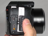
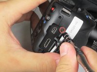
Pull back the rubber facing to access the A/V and HDMI output compartment.
-
Remove 1-3.4mm screw inside the compartment using a Phillips #000 screwdriver.
-
-
-
-
Once all screws are removed, pull the back facing off with your fingers.
-
-
-
Remove 3-4.4 mm screws that secure the small metal plate using a Phillips #000 screwdriver.
-
-
-
Carefully pop out the LCD screen with your fingers.
-
-
-
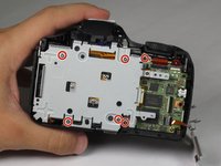
Remove 6-4.4 mm screws that secure the metal cover using a Phillips #000 screwdriver.
-
Remove 2-2.5 mm screws that secure the back panel using a Phillips #000 screwdriver.
-
After all 8 screws are removed, pull the metal plate out with your fingers.
-
-
-
Unlcip the large cable by pulling up on the metal part with your finger.
-
Slide out the 2 smaller cables with your fingers.
-
-
-
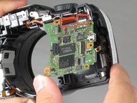
Lift up the lens by grabbing the sides with your fingers.
-
-
-
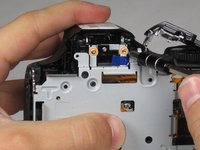
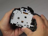
Remove 1-2.5 mm screw using a Phillips #000 screwdriver.
-
-
-
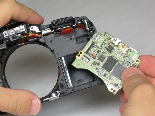
Disconnect the two orange serial cables at the top of the motherboard using your fingers.
-
Gently remove the motherboard using your fingers.
-


To reassemble your device, follow these instructions in reverse order.
To reassemble your device, follow these instructions in reverse order.
crwdns2935221:0crwdne2935221:0
crwdns2935229:03crwdne2935229:0
crwdns2915084:0crwdne2915084:0

Baylor, Team 4-4, Williams Fall 2015 crwdns2935289:0Baylor, Team 4-4, Williams Fall 2015crwdne2935289:0
BU-WILLIAMS-F15S4G4
crwdns2931471:04crwdne2931471:0
crwdns2935297:06crwdne2935297:0