crwdns2915892:0crwdne2915892:0
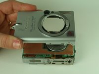
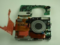
This guide illustrates how to remove the battery casing.
crwdns2942213:0crwdne2942213:0
-
-
-
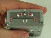
On the backside of the camera, remove the 4.75 mm screw that sits at the top right corner.
-
Remove the four 4.75 mm screws that sit at the bottom of the camera.
 crwdns2952109:0crwdne2952109:0
-
-
-
On the side of the camera, remove the two 4.75 mm screws that sit near the USB digital terminal.
-
-
-
On the side of the camera, remove the four 4.75 mm screws that sit near the wrist strap mount.
-
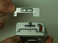
Remove the two small metal plates, which the four screws hold in place.
-
-
crwdns2935267:0crwdne2935267:0Tweezers$4.99
-
Remove the small black plastic piece and set it aside. If necessary, use tweezers to remove the small black plastic piece.
-
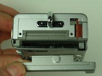
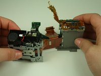
Detach the front case and back case.
-
-
-
Remove the 3.5 mm screw that sits on the metal plate at the bottom of the camera.
-
Remove the two other 3.5 mm screws that sit on the side, to the left of the screw you just removed.
-
-
-
A ribbon cable attaches to the metal plate and to the main circuit board, on the front of the camera.
-
Gently release the black latch.
-
Remove the ribbon cable and metal plate assembly.
-
-
-
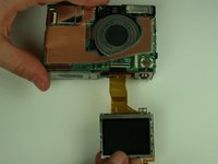
On the backside of the camera, remove the 3.5 mm screw that sits to the left of the viewfinder and above the LCD screen.
-
Remove the second 3.5 mm screw that sits directly above the LCD screen.
-
Gently detach the ribbon cable.
-
-
-
-
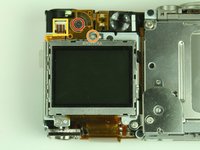
Locate the ribbon cable on the main circuit board, which sits below the lens.
-
Gently release the black latch on the ribbon cable connector and detach the ribbon cable.
-
-
-
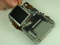
Remove the LCD screen and set it aside.
-
-
-
-
-
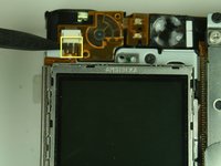
Locate the ribbon cable connection to the left of the lens on the main circuit board.
-
Gently flip open the black latch on the connector and detach the ribbon cable.
-
-
-
Locate the three ribbon cables on the main circuit board. Gently flip open these black latches.
-
Gently disconnect the ribbon cables.
-
-
-
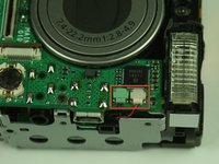
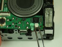
Locate the white and green connectors underneath the flash.
-
Gently disconnect these connectors.
-
-
-
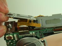
Using a spudger, carefully pry the shutter button assembly from the camera.
-
-
-
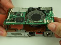
Remove the four screws securing the main circuit board to the rest of the camera. (In the image, some of the screws have already been removed)
-
-
-
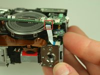
Gently lift the bottom of the main circuit board, the side without the soldered attachment points, like a hinge.
-
Locate the white ribbon cable attached to the underside of the main circuit board.
-
Gently remove the white ribbon cable from the connector.
-
-
-
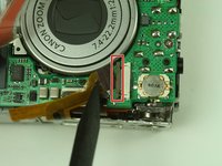
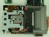
Locate and remove the three 3.45mm screws on the backside of the camera that secure the CF card slot.
-
Make note of the orientation of the ribbon cable connected to the CF card slot. You will need this for re-assembly.
-
Gently remove the CF card slot.
-
-
-
Orient the camera so you are looking at the top.
-
Locate the white connector that attaches the flex circuit to the capacitor.
-
Disconnect the connector.
-
-
-
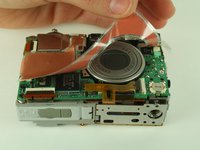
Adhesive tape attaches the flex circuit to the top of the camera. Gently un-stick the flex circuit from the tape, but do not completely remove the flex circuit.
-
-
-
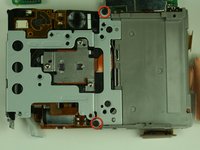
Remove the two 3.45mm screws located on the backside of the camera.
-
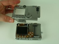
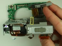
Separate the battery compartment and the lens-flash assembly.
-
-
-
Set the lens-flash assembly aside.
-
De-solder the two soldered ribbon cables attached to the motherboard.
-
Separate the motherboard and battery case.
-
-
-
Replace battery casing
-
-


To reassemble your device, follow these instructions in reverse order.
crwdns2935287:0crwdne2935287:0

Cal Poly, Team 5-19, Amido Winter 2011 crwdns2935289:0Cal Poly, Team 5-19, Amido Winter 2011crwdne2935289:0
CPSU-AMIDO-W11S5G19
crwdns2931471:04crwdne2931471:0
crwdns2935297:06crwdne2935297:0