crwdns2915892:0crwdne2915892:0
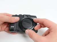
Use this guide to replace the lens assembly. A broken lens may cause photos to be blurry, contain artifacts, or other defects in quality and composition.
crwdns2942213:0crwdne2942213:0
-
-
Open the battery flap on the bottom of the camera by applying pressure and pushing in the direction of the arrow.
-
Remove your finger and allow the flap to pop open.
-
-
-
Push the brown lever so that it pivots counterclockwise.
-
Grip and remove the battery.
-
-
-
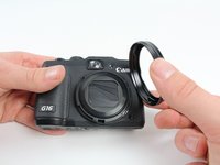
Remove the ring around the lens by simultaneously pressing the black button located at the bottom right of the ring and rotating the ring counterclockwise.
-
-
-
Remove the four 3.3 mm screws on the bottom of the camera using a Phillips #00 screwdriver.
-
-
-
Remove the 3.3 mm screw on the right side of the viewfinder using a Phillips #00 screwdriver.
-
-
-
Remove the two 3.3 mm screws near the speaker using a Phillips #00 screwdriver.
-
-
-
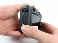
Open the port cover by lifting up the tab with your finger and remove the 7.3 mm screw underneath the cover using a Phillips #00 screwdriver.
-
Remove the other 3.3 mm screw below the ports using a Phillips #00 screwdriver.
-
-
-
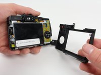
Using your fingers, carefully pull the the back cover off by grabbing the bottom left of the back cover and pulling outwards.
-
-
-
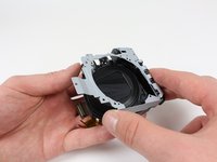
Using your fingers, carefully pry the front cover off starting at the bottom right.
-
-
-
Remove the 3.8 mm screw at the bottom right of the port cover housing using a Phillips #00 screwdriver.
-
Lift away the port cover housing.
-
-
crwdns2935267:0crwdne2935267:0Tweezers$4.99
-
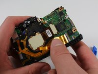
Reorient the camera so that you are looking at the back.
-
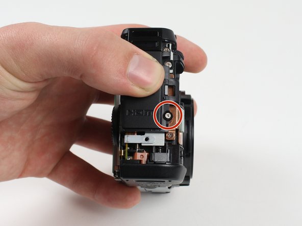
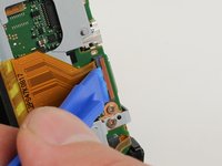
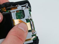
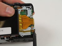
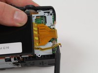
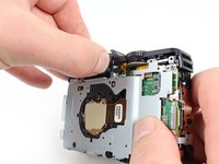
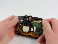
Unplug the button circuit board from the motherboard by unlocking the ZIF connector (gently lift the brown lock that keeps the cable in place).
-
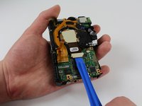
Pull the connector downwards with the tweezers.
This is not completely correct. In order to pull the connector down without force, the little grey tap on the top of the connectorbox has to be flipped up.
This particular step cost me the connection to the button curcuit board. I would be grateful for an indication of where I can buy a replacement. Thanks.
You saved my connection. Thank you. iFixit... I'm somewhat disappointed these steps haven't been corrected.
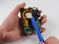
It's worth noting that I had no luck with tweezers when attempting to remove the ribbon cable. The correct procedure would be to carefully lift the plastic clip with an iFixit spudger and then continue to step 12. The ribbon cable will pull out gently without any other coercion.
The clip is a red/terracotta colour, this should be lifted like a lid (the hinge is mounted in the grey housing). The connector should be pulled downward as described. This should definitely be corrected. Thanks for the comments to assist. I added this for extra clarity on the colours only.
just destroyed it!, thanks for nothing...
Lool, just noticed on the pictures you destroyed your connector as well. Good for you for posting faulty guide.
-
-
-
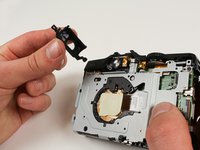
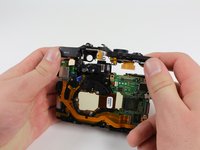
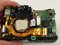
Remove the 3.0 mm screw on the top of the button memory board using a Phillips #00 screwdriver.
-
Remove the 2.8 mm screw on the bottom of the button memory board using a Phillips #00 screwdriver.
-
-
-
Lift the button circuit board away from the camera.
-
-
-
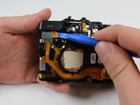
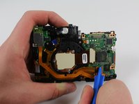
Unlock the ZIF connector for the large connector ribbon by lifting up on the brown flap with the plastic opening tool.
-
Gently pull the connector straight out of the housing with your fingers.
-
-
-
-
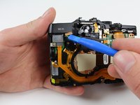
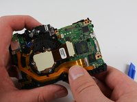
Unplug the small connector ribbon by pulling the cable outwards from the camera using a spudger or your fingers.
Be careful with this step. I broke the black connector off the motherboard for the small ribbon cable. It is very fragile. You might want to push down on the black connector to hold it in place while gently pulling the ribbon to the right to extract it from the connector. Don’t let the black connect pull up or twist.
-
-
-
Gently lift the LCD away from the camera housing.
-
-
-
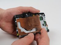
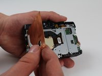
Lift and remove the copper EMI shield.
the screw in the upper right corner disappears magically between the two photos in this step ;) .
-
-
-
Reorient the camera so that you are looking at the front.
-
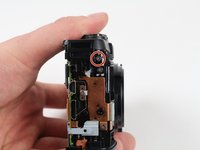
Remove the 2.8 mm screw right above the screw holding the lens on using a Phillips #00 screwdriver.
-
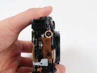
Remove the 3.3 mm black screw to the left of the front viewfinder using a Phillips #000 screwdriver.
-
-
-
Reorient the camera so that you are looking at the back.
-
Remove the 6.8 mm screw to the left of the rear viewfinder using a Phillips #00 screwdriver.
-
Remove the 5.2 mm screw to the right of the rear viewfinder using a Phillips #00 screwdriver.
Somewhere between this step, and Step 21 the screw in the top right (right and up slightly of the orange circled 5.2mm screw) is removed. Suggest doing it here! Same with the one immediately to the right of that.
Perfect Comment of Phil Howard! In this moment is necessary remove other screw positioned upper-right
-
-
-
Remove the top 2.3 mm screw from the side with the ports using a Phillips #00 screwdriver.
-
Remove the 4 mm screw right below the one you just removed using a Phillips #00 screwdriver.
you don’t have to remove the 2.3mm screw in this step, it’s just connected to the top cover
-
-
-
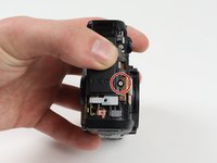
Reorient the camera so that you are looking at the back of the camera.
-
Remove the rear viewfinder casing by firmly gripping it and pulling it out bottom first.
-
-
-
Remove the newly uncovered 2.8 mm screw from the right of the viewfinder using a Phillips #00 screwdriver.
-
Remove the 4.9 mm screw from top right of the metal casing on the back using a Phillips #00 screwdriver.
-
Remove the 4.3 mm screw from bottom right of the metal casing on the back using a Phillips #00 screwdriver.
-
Remove the newly uncovered screws from the right of the viewfinder using a Phillips #00 screwdriver. (Note, they're already removed on the picture)
It’s necessary remove olso other little screw positioned on the orange screw ;)
The right-most screw encircled in green requires a smaller driver than the rest of the screws in this step.
colors are messed up
-
-
-
Remove the 2.7 mm screw from the bottom of the camera using a Phillips #00 screwdriver.
-
-
-
Reorient the camera so that you are looking at the side with the black felt circle.
-
Remove the 2.8 mm screw from the right side of the camera if you are looking at the front lens using a Phillips #00 screwdriver.
-
-
-
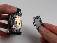
Reorient the camera so that you are looking at the back of the camera.
-
Remove the metal casing from the back by lifting it away from the camera.
-
-
-
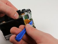
Disconnect the cable on the top of the motherboard by lifting it up vertically using a plastic opening tool.
-
-
-
Disconnect the cable on the back of the camera to the left of the viewfinder by lifting it up vertically using a plastic opening tool.
-
-
-
Remove the top portion of the casing by firmly grasping it and pulling it upward to lift it off.
At this point the tiny little ribbon cable and flat-flex with two diodes on it (face sensor?) may still be attached to the right of the viewfinder lens. It may just be caught on the two locating pegs. Pull it gently upwards before removing the top.
Same precisation of Phil Howard! Please attention at that flat-flex, raise flat before remove machine top!!!!!
-
-
-
Open the two ZIF connectors by flipping them up using a plastic opening tool on the motherboard.
-
Disconnect the two cable ribbons by pulling them straight out.
-
-
-
Disconnect the lens cable from the motherboard by lifting it up vertically from the motherboard using a plastic opening tool.
Must remove 2 screw:
1) bottom-left (little head, long shaft)
"2) upper-left (big head, short shaft)
for remove motherboard
-
-
crwdns2935267:0crwdne2935267:0Tweezers$4.99
-
Remove the small cable towards the top by pulling it straight out of its connector using tweezers or your fingers.
-
Remove both Screws on the bottom side of the motherboard
-
-
-
Lift the motherboard out of the camera.
It's missing the step to remove two screw that fixes the motherboard
Probably would be helpful to remove the memory card before doing this step. I’m not sure that was suggested previously.
Also, just opening the battery compartment door may be helpful in removing the main board.
You can clearly see that one socket is missing at the top of the plate. It was destroyed some steps earlier.
-
-
-
Reorient the camera so that black lens cover is facing you with viewfinder on top.
-
Remove the four 5.3 mm screws around the lens using a Phillips #00 screwdriver.
-
Remove the 3.8 mm screw above the lens using a Phillips #00 screwdriver.
-
-
-
Remove the black plastic cover surrounding the lens by gripping and lifting upwards.
-
-
-
Remove the black 3.8 mm screw on the far left side using a Phillips #000 screwdriver.
-
-
-
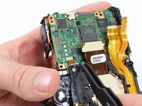
Grip the left and right halves of the camera and wiggle them apart.
You can see that a small screw is missing over the lens. It must have been removed between steps. poor quality.
-
-
-
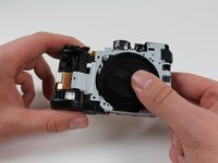
Pick up the half of the camera that contains the lens.
-
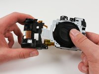
Remove top 4 mm screw from the strap holder using a Phillips #00 screwdriver.
-
Remove the middle 3.8 mm screw next to the left speaker using a Phillips #00 screwdriver.
-
-
-
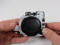
Remove the cable strap bracket by lifting it away.
-
-
-
Disconnect the cable in the top left by pulling it straight out of its connector.
-
-
-
Lift the metal frame away from the lens.
-


To reassemble your Canon PowerShot G16, follow these instructions in reverse order.
To reassemble your Canon PowerShot G16, follow these instructions in reverse order.
crwdns2935221:0crwdne2935221:0
crwdns2935229:013crwdne2935229:0
crwdns2915084:0crwdne2915084:0

Cal Poly, Team 70-6, Forte Winter 2016 crwdns2935289:0Cal Poly, Team 70-6, Forte Winter 2016crwdne2935289:0
CPSU-FORTE-W16S70G6
crwdns2931471:04crwdne2931471:0
crwdns2935297:07crwdne2935297:0
crwdns2947412:09crwdne2947412:0
A well understood and skillfully documented and photographed guide. Not for the faint hearted, but that's not the author's fault!
I would like to thank you for the guide. I used this guide yesterday to change the lenses of a G15. It has some differences, but your guide helped me a lot. I'm not a technician and I almost gave up on the way, but in the end everything worked out. Thanks!
You haven’t disassembled the lens yet or exposed the sensor which may have dust on it and be in need of cleaning or even replacement. How is that done, wise guy?
Anybody knows a good and reliable seller where i can buy the lens replacement part for the canon g16? Thanks!
To be clear, can this procedure be used to replace a lens that has got stuck due to a drop? And a source(s) for the replacement part would be great.
Just did it. Except 7 forgotten screws it was right. Just why doing it if we don't finish it fully? I mean step 40 the lens is still with the viewfinder sensor and any wires and going further is really complicated.
Thanks anyway as this tuto helped me a lot to see the different parts of my camera, but still looking for the Date battery
How dos one repair/replace the lens curtain? I mean the 6 leaves and 2 springs that cover the lens when it is retracted into the camera.
This is not complete. Missing the last part of actually removing the lens.
I wanted to change the lens, and I did with a big help from youtube. When reassembling it turned out I destroyed a motherboard connector at the very beginning because of this 'guide'.