crwdns2915892:0crwdne2915892:0
Use this guide to replace the Canon PowerShot A75's upper motherboard.
crwdns2942213:0crwdne2942213:0
-
-
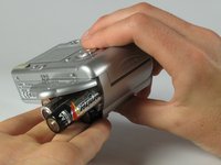
Turn the camera over and locate the "BATT OPEN" sliding switch.
-
-
-
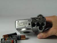
Remove the three 2.5mm screws on the bottom of the camera.
-
-
-
Remove the 3.8mm screw underneath the flap that covers the A/V port.
-
-
-
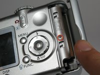
Remove the 2.4mm screw located underneath the cover of the memory card slot.
-
-
-
Open the memory card slot by sliding it laterally until you hear a click.
-
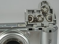
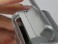
Remove the 5.9mm screw in the upper corner of the memory card slot.
-
-
-
Remove the two 4.1mm screws at the bottom of the battery flap.
-
-
-
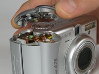
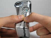
Lift the shutter button and speaker part from the top of the camera.
-
-
crwdns2935267:0crwdne2935267:0Tweezers$4.99
-
Using a pair of tweezers, grab the plug that connects the speaker to the camera and gently pull it out.
-
-
-
-
Remove the rightmost 4.2mm screw underneath the battery cover, not the center screw.
-
-
-
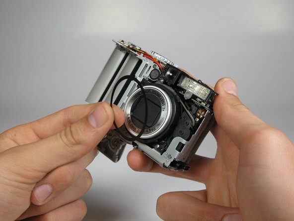
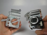
Separate the back casing and front casing of the camera using your hands.
-
-
-
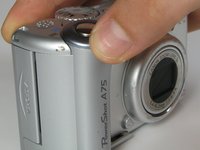
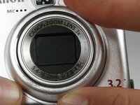
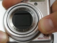
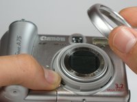
On the front of the camera, press the button on the lower left of the lens.
-
Twist the outer lens casing counter-clockwise and slide it out.
-
-
-
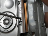
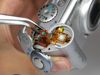
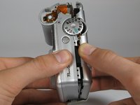
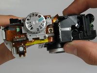
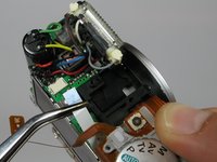
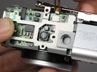
Remove the 4.4mm screw directly behind the eyepiece on the top of the camera.
-
Remove the 4.3mm screw to the right of the eyepiece housing in the crack in between the eyepiece and a ribbon cable on top of the camera.
-
-
-
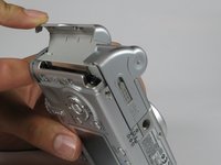
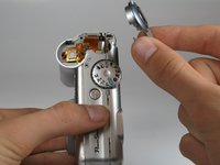
Gently wiggle the eyepiece out of its place. It should snap out of place.
-
-
crwdns2935267:0crwdne2935267:0Tweezers$4.99
-
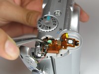
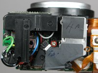
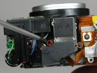
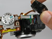
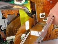
Locate the white cable on top of the camera where the eyepiece was.
-
Using tweezers, grasp the white cable as close to the connection point as possible and gently remove the cable.
-
Remove the 2.9mm screw directly underneath the white cable.
-
-
-
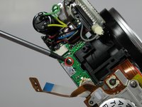
Remove the 4.2mm screw directly under the battery flap.
-
-
-
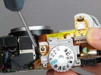
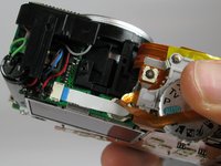
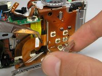
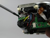
Remove the 3.4mm screw inside a deep hole on the back copper panel beneath the circular mode switcher.
-
-
-
Remove 2.5mm the screw in the silver housing on the bottom of the camera. This screw is holding the back panel in.
-
-
-
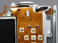
Remove the 3.4mm screw near the bottom of the back face of the camera on the copper ribbon.
-
Remove the 2.9mm screw on the back face of the camera in the bottom left corner.
-
-
-
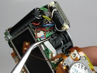
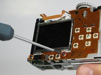
Locate the copper ribbon cable attaching the LCD screen to the bottom motherboard.
-
Grasp the cable near the white connector and gently remove the cable.
-
-
-
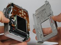
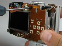
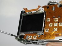
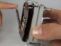
Gently pull back the LCD screen to around 45 degrees from the back of the camera.
-
Locate the larger ribbon cable connecting the screen to the body of the camera.
-
-
-
Gently grasp and pull the cable from the motherboard. The cable should easily slide out.
-
The LCD should now be out after the cable is removed.
-
-
-
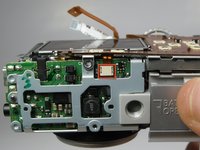
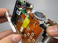
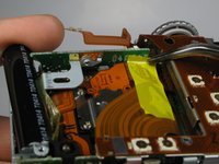
Remove the 3.5mm screw found near the capacitor and the flash unit.
-
-
-
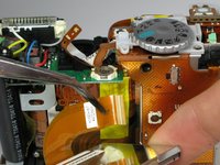
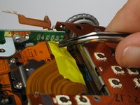
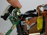
Carefully remove the yellow piece of adhesive tape connected to the motherboard.
-
-
-
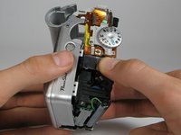
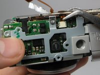
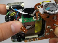
Remove the main motherboard from the casing, which is connected to the flash unit, capacitor, and bottom motherboard.
-
-
-
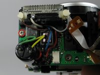
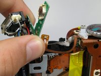
Unsolder any remaining wires on the motherboard to completely remove it.
-


To reassemble your device, follow these instructions in reverse order.
crwdns2935287:0crwdne2935287:0

Cal Poly, Team 17-30, Amido Spring 2012 crwdns2935289:0Cal Poly, Team 17-30, Amido Spring 2012crwdne2935289:0
CPSU-AMIDO-S12S17G30
crwdns2931471:05crwdne2931471:0
crwdns2935297:012crwdne2935297:0