crwdns2915892:0crwdne2915892:0
Use this guide to replace the Canon PowerShot A75's LCD screen.
crwdns2942213:0crwdne2942213:0
-
-
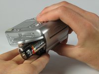
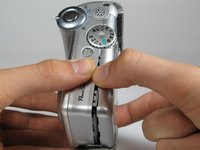
Turn the camera over and locate the "BATT OPEN" sliding switch.
-
-
-
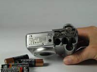
Remove the three 2.5mm screws on the bottom of the camera.
-
-
-
Remove the 3.8mm screw underneath the flap that covers the A/V port.
-
-
-
Remove the 2.4mm screw located underneath the cover of the memory card slot.
-
-
-
Open the memory card slot by sliding it laterally until you hear a click.
-
Remove the 5.9mm screw in the upper corner of the memory card slot.
-
-
-
Remove the two 4.1mm screws at the bottom of the battery flap.
-
-
-
-
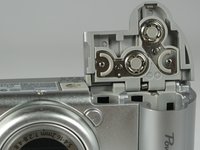
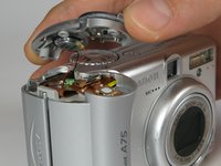
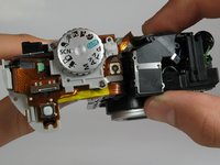
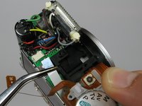
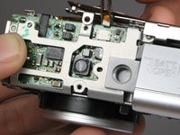
Lift the shutter button and speaker part from the top of the camera.
-
-
crwdns2935267:0crwdne2935267:0Tweezers$4.99
-
Using a pair of tweezers, grab the plug that connects the speaker to the camera and gently pull it out.
-
-
-
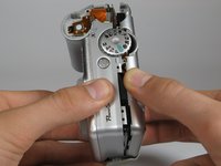
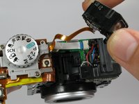
Remove the rightmost 4.2mm screw underneath the battery cover, not the center screw.
-
-
-
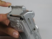
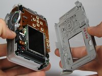
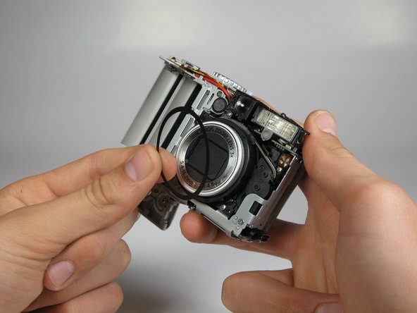
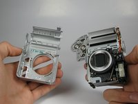
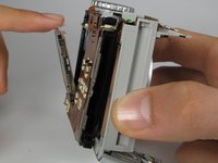
Separate the back casing and front casing of the camera using your hands.
-
-
-
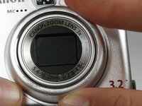
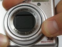
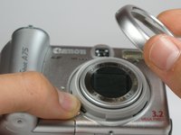
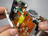
On the front of the camera, press the button on the lower left of the lens.
-
Twist the outer lens casing counter-clockwise and slide it out.
-
-
-
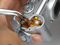
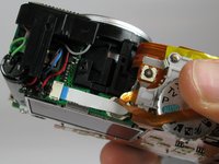
Remove the 4.4mm screw directly behind the eyepiece on the top of the camera.
-
Remove the 4.3mm screw to the right of the eyepiece housing in the crack in between the eyepiece and a ribbon cable on top of the camera.
-
-
-
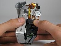
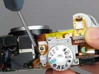
Gently wiggle the eyepiece out of its place. It should snap out of place.
-
-
crwdns2935267:0crwdne2935267:0Tweezers$4.99
-
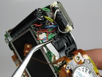
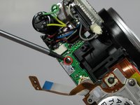
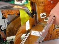
Locate the white cable on top of the camera where the eyepiece was.
-
Using tweezers, grasp the white cable as close to the connection point as possible and gently remove the cable.
-
Remove the 2.9mm screw directly underneath the white cable.
-
-
-
Remove the 4.2mm screw directly under the battery flap.
-
-
-
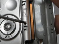
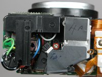
Remove the 3.4mm screw inside a deep hole on the back copper panel beneath the circular mode switcher.
-
-
-
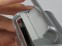
Remove 2.5mm the screw in the silver housing on the bottom of the camera. This screw is holding the back panel in.
-
-
-
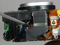
Remove the 3.4mm screw near the bottom of the back face of the camera on the copper ribbon.
-
Remove the 2.9mm screw on the back face of the camera in the bottom left corner.
-
-
-
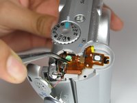
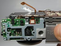
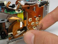
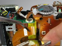
Locate the copper ribbon cable attaching the LCD screen to the bottom motherboard.
-
Grasp the cable near the white connector and gently remove the cable.
-
-
-
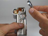
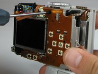
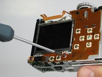
Gently pull back the LCD screen to around 45 degrees from the back of the camera.
-
Locate the larger ribbon cable connecting the screen to the body of the camera.
-
-
-
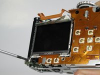
Gently grasp and pull the cable from the motherboard. The cable should easily slide out.
-
The LCD should now be out after the cable is removed.
-


After all the steps are done, you can make any necessary repairs to the LCD screen. To reassemble your device, follow these instructions in reverse order.
After all the steps are done, you can make any necessary repairs to the LCD screen. To reassemble your device, follow these instructions in reverse order.
crwdns2915084:0crwdne2915084:0

Cal Poly, Team 17-30, Amido Spring 2012 crwdns2935289:0Cal Poly, Team 17-30, Amido Spring 2012crwdne2935289:0
CPSU-AMIDO-S12S17G30
crwdns2931471:05crwdne2931471:0
crwdns2935297:012crwdne2935297:0