crwdns2915892:0crwdne2915892:0
This guide will involve complete disassembly of the camera.
crwdns2942213:0crwdne2942213:0
-
-
-
Slide the switch on the battery cover labeled "CARD/BATT. OPEN." to the right.
-
While still holding the switch, pull the cover down, allowing it to release and open.
 crwdns2952109:0crwdne2952109:0
-
-
-
Tilt the camera slightly to allow the batteries to fall out.
-
-
-
Press on and release the memory card to eject it.
-
-
-
-
-
Unscrew the 5mm Phillips #00 screw from the bottom of the camera.
-
-
-
Unscrew the three 2mm Phillips #00 screws that are located on the bottom of the camera.
-
-
-
Remove the 4mm Phillips #00 screw that is located on the left side of the camera, if the display screen is facing you.
-
-
-
Take out the 4mm Phillips #00 screw under the rubber flap on the right end of the camera.
-
-
-
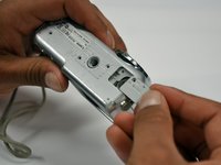
Remove the second battery cover on the bottom of camera.
-
Take the silver battery out of the camera.
-
-
-
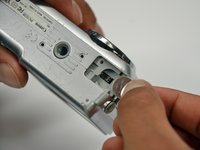
Remove the 4mm Phillips #00 screw on the inside of the flap that hides the battery and memory card slots.
-
Remove the light grey, plastic piece.
-
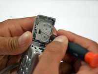
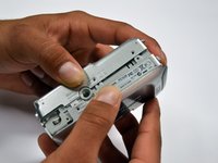
Remove the plastic portion of the battery flap cover. The metal piece will remain attached.
-
-
-
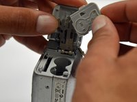
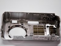
Slightly pull on each side of the camera. It should loosen up and come apart.
-
If it does not pull apart right away, use a little more force.
-
Do not give up!
-
-
-
-
-
Remove the back case of the camera by pulling from the top.
-
-
-
-
-
-
Remove the 4mm Phillips #00 screw from above the ribbon.
-
-
-
Gently peel off the blue tape on the top of the LCD screen.
-
-
-
Remove the 4mm Phillips #00 screw previously concealed by the blue tape.
-
-
-
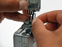
Gently lift the LCD screen off of the front casing by pulling up a tab on the side of the camera.
-
-
-
Using a spudger, lift the grey tabs to allow the ribbon to slide out.
-
-
-
Since the tabs have been lifted, the ribbon should now slide out out easily.
-
-
-
-
-
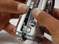
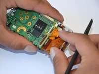
Remove the 5mm Phillips #00 screw located above the small black piece on the right side of the mother board.
-
-
-
Remove the 4mm Phillips #00 screw at the bottom of the black piece.
-
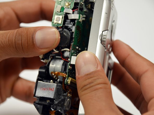
Detach the black piece that the screws previously held in place.
-
-
-
Remove the 5mm Phillips #00 screw in the middle of the motherboard.
-
-
-
Remove the 5mm Phillips #00 screw that holds the metal piece to the bottom of the camera .
-
-
-
Remove the 5mm Phillips #00 screw that is located on the top of camera.
-
-
-
Remove the 2mm Phillips #00 screw that is located on the far left of the motherboard.
-
-
-
Remove the 5mm Phillips #00 screw near the bottom left of the motherboard.
-
-
-
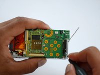
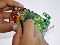
Using a spudger, unlock the locking mechanism that holds the lower orange ribbon in place.
-
Once unlocked, slide out the ribbon.
-
-
-
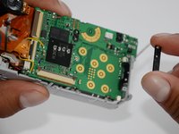
Using a spudger, unlock the locking mechanism that holds the upper orange ribbon in place.
-
Once unlocked, slide out the ribbon.
-
-
-
All that is required is to unsolder the few remaining wires. Then, the motherboard will be ready to be replaced!
-
-
-
-
-
Remove the six 2mm Phillips #00 screws that are located under the motherboard.
-
-
-
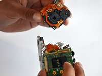
Remove the 4mm Phillips #00 screw that is located under the now disconnected top orange ribbon.
-
The lens piece can now be removed from the camera.
-
-
-
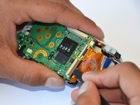
Remove the 5mm Phillips #00 screw on the back of the lens piece.
-
-
-
Remove the 2mm Phillips #00 screw on the bottom of the lens piece.
-
-
-
Remove the two 2mm Phillips #00 screws on the top of the lens piece.
-
-
-
Gently slide off the black piece surrounding the lens. The lens is now disassembled!
-
-


To reassemble your device, follow these instructions in reverse order.
crwdns2935221:0crwdne2935221:0
crwdns2935229:04crwdne2935229:0
crwdns2935287:0crwdne2935287:0

Cal Poly, Team 19-42, Regan Winter 2013 crwdns2935289:0Cal Poly, Team 19-42, Regan Winter 2013crwdne2935289:0
CPSU-REGAN-W13S19G42
crwdns2931471:04crwdne2931471:0
crwdns2935297:012crwdne2935297:0
crwdns2947410:01crwdne2947410:0
please put a big warning note on the step after removing the blue tape from the lens. and the next on is where you lift something on the mother board with a spluger..something like that. well i used a screwdriver and got such a big electrical shock.... scared the crapola out of me. please make a note .... can get electrical shock....
Gaby - crwdns2934203:0crwdne2934203:0 crwdns2950251:0crwdne2950251:0