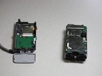
crwdns2915892:0crwdne2915892:0
We will take out the broken motherboard and replace it with a new one.
crwdns2942213:0crwdne2942213:0
-
-
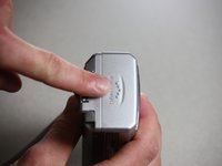
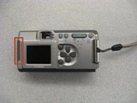
Use a Phillips #00 screwdriver to remove the two screws located at the bottom of the camera.
-
-
-
Locate the screw and the rubber covering on the left side of the camera. Slide the rubber covering to expose a second screw.
-
Remove the two screws with the Phillips #00 screwdriver.
-
-
-
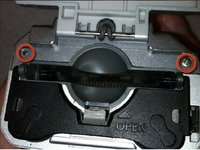
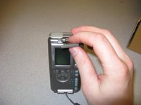
Open the battery compartment on the right side of the camera by pushing slightly in the direction of the arrow.
-
Remove the two screws by the memory card slot using the Phillips #00 screwdriver.
-
-
-
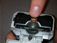
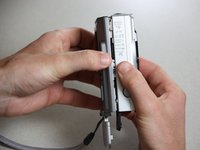
Pull the grey tab towards the back of the camera. Lift the black cover to expose the battery slots.
-
Remove the two visible screws with the Phillips #00 screwdriver.
-
-
-
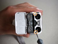
Remove the screen battery located to the left of the screen.
-
Set the screen battery aside for reassembly
-
-
-
-
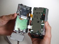
Gently pull the camera apart from the top.
-
-
crwdns2935267:0crwdne2935267:0Tweezers$4.99
-
Locate the black tabs on either side of the white ribbon.
-
Use the metal tweezers to gently move these tabs to the outside edges of the ribbon.
-
Gently pull the white ribbon out from its connection.
-
-
-
Locate the black tabs on either side of the orange ribbon.
-
Use the metal tweezers to gently move these tabs to the outside edges of the ribbon.
-
Gently pull the orange ribbon out of its connection.
-
-
-
Use a Phillips head screwdriver to remove the four screws from the corners of the LCD.
-
-
-
Use the iFixit plastic opening tool to lift the LCD away from the back case.
-
-
-
Use a soldering iron to remove the LCD from the orange cable connected to the back of the camera.
-
Use the soldering iron to attach your new LCD in place.
-
-
-
Follow the prerequisite instructions for Disassembling the Canon PowerShot A200 Case and for the Canon PowerShot A200 LCD Display Replacement.
-
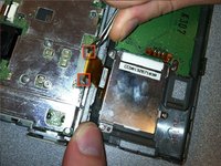
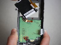
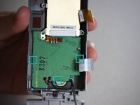
Once the LCD Display has been removed, use the soldering kit to desolder the red and black connections attached to the green motherboard.
-
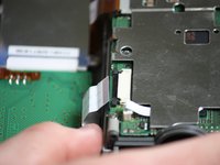
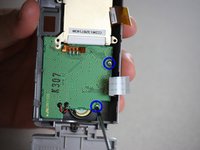
Use the Phillips head screwdriver to remove the two screws in the motherboard. Set the screws aside.
-
-
-
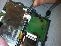
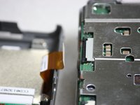
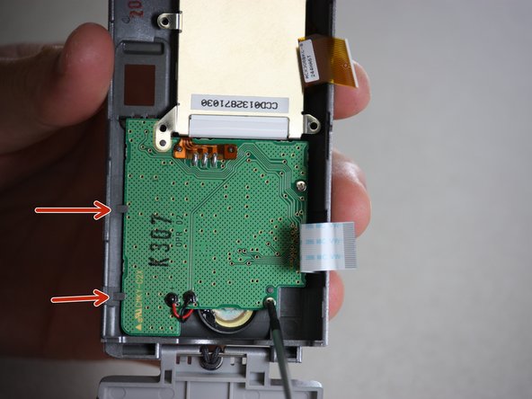
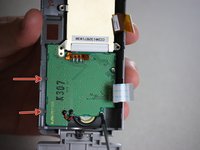
Use the plastic opening tool to carefully pry the motherboard out of its place, proceeding from the indicated points. Pull gently, as to not destroy any of the other internal parts of the camera.
-
Insert the new green motherboard in place, making sure it fits snugly under the grey tabs at the edge of the camera case.
-
Reassemble the camera following these instructions in reverse order, as well as the instructions in the prerequisite guides.
-


To reassemble your device, follow these instructions in reverse order.
To reassemble your device, follow these instructions in reverse order.
crwdns2915084:0crwdne2915084:0

Cal Poly, Team 7-37, Regan Winter 2011 crwdns2935289:0Cal Poly, Team 7-37, Regan Winter 2011crwdne2935289:0
CPSU-REGAN-W11S7G37
crwdns2931471:04crwdne2931471:0
crwdns2935297:010crwdne2935297:0