crwdns2915892:0crwdne2915892:0
This guide will detail the process of replacing the motherboard. Replacing the motherboard is a more involved process and should not be done unless your are sure there is an issue with the motherboard.
crwdns2942213:0crwdne2942213:0
-
-
Locate the battery cover at the bottom of the camera.
-
Pull down on the black tab to open the cover.
-
-
-
Push the grey tab on the right side of the battery.
-
Remove the battery from the slot.
-
-
-
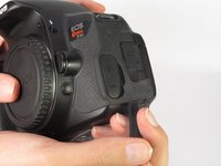
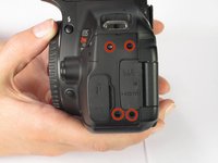
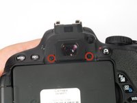
Use the spudger to pry off the rubber grip and reveal the screws.
-
Unscrew the four 5.5mm Torx screws using the Torx T6 screwdriver.
-
-
-
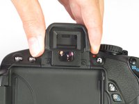
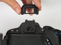
Pull off the plastic cover from the viewfinder.
-
Unscrew the two 3.4mm JIS screws using the JIS #00 screwdriver.
-
-
-
Remove the following screws from the device using the JIS #00 screwdriver:
-
Two 3.4mm JIS screws.
-
Two 5.9mm JIS screws.
On my camera, both the outer screews were 5.9 mm long.
I can confirm the comment from 03/14/2015: Both outer screews are long.
-
-
-
-
Remove the following screws from the device using the JIS #00 screwdriver:
-
One 3.4mm JIS screw.
-
One 5.9 mm JIS screw.
-
-
-
Remove the rear panel from the camera.
-
-
-
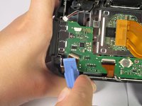
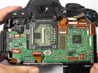
In the lower right corner of the mother board, detach the blue cable.
-
Then detach the ribbon cable going from the motherboard to the rear panel.
-
-
-
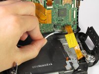
In the upper left corner of the motherboard, remove the small multicolored wire from the motherboard.
-
-
-
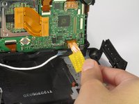
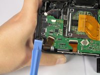
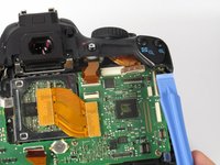
Use the plastic opening tool to flip up ribbon cable connector.
-
Gently disconnect the ribbon cable by pulling it away from the motherboard.
-
-
-
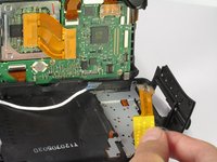
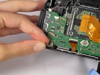
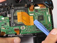
In the upper right corner of the motherboard, use the plastic opening tool to remove the clear cable connector from the motherboard.
-
-
-
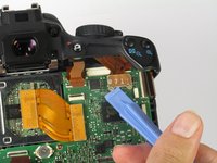
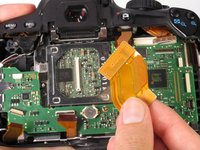
Use the plastic opening tool to remove the ribbon cable connecting the image sensor to the motherboard.
-
-
-
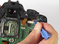
Use the plastic opening tool to push on the indents of the plastic header to disconnect from the motherboard.
-
Make sure all cables are disconnected from the motherboard.
-
-
-
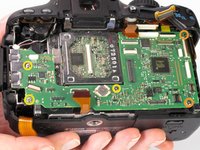
Remove the following screws from the motherboard using the JIS #00 screwdriver:
-
Two 3.9mm JIS screws.
-
Three 2.9mm JIS screws
-
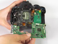
Gently pull the motherboard out of the camera.
I was wondering how did you get to loosen the 3.9mm Phillips screw on the top right.
Fixed that, the orange marker was a bit off, it was on an alignment pin instead of the actual screw which was just a bit more to the right.
I cannot reach the 3.9mm screw with any tool because it is underneath of the plastic body that holds the zoom +/- buttons. How old you remove that top right motherboard screw?
I hate to bring up an old question, but did you ever manage to get this screw off with your camera? I am working on mine yet I am about to simply drill through the plastic under the zoom buttons.
You have to remove the top part of the camera body to reach the screw. It is also much easier to reconnect flat cables.
Where can I find a replacement board. I cannot find one anywhere!
Same here, how to remove this top-right orange 3.9mm phillips screw?
If top has to be removed, how to do that? It’s not visually obvious to me at the moment.
Also, really where to get the replacement MB?
That last top-right screw is actually impossible to remove - need to take off the top cover. Follow this guide:
-


To reassemble your device, follow these instructions in reverse order.
To reassemble your device, follow these instructions in reverse order.
crwdns2935221:0crwdne2935221:0
crwdns2935229:016crwdne2935229:0
crwdns2915084:0crwdne2915084:0

Cal Poly, Team 12-33, Maness Spring 2014 crwdns2935289:0Cal Poly, Team 12-33, Maness Spring 2014crwdne2935289:0
CPSU-MANESS-S14S12G33
crwdns2931471:04crwdne2931471:0
crwdns2935297:014crwdne2935297:0
crwdns2947412:02crwdne2947412:0
This guide gets an upvote.
It's the first camera disassembly guide I've seen so far on ifixit that includes the single most important precaution: the camera has a body cap fitted to avoid dust, dirt or other objects getting into the mirror box. Bravo!
Where can we buy the parts?