crwdns2915892:0crwdne2915892:0
This guide shows you how to replace the top cover of the camera. This is also useful if you are trying to repair or replace a particular part located on the top cover, or are trying to gain access to a different component further inside the camera.
Note that the Phillips #000 screwdriver is marked as an optional tool as you can always use the JIS #000 screwdriver in its place (JIS screwdrivers won't damage Phillips head screws).
crwdns2942213:0crwdne2942213:0
-
-
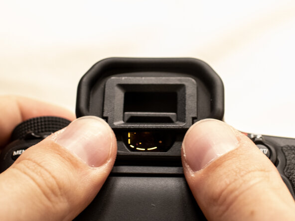
Before beginning, remove the battery and SD card from the camera.
-
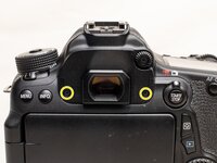
Using your thumbs, push up on the eyepiece to remove it.
-
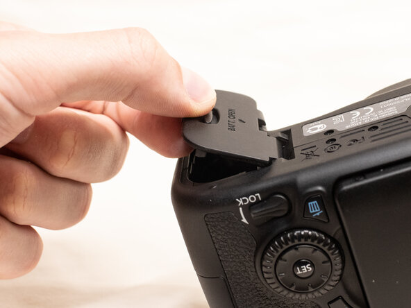
Remove the battery door.
-
Open the battery door to about a 35° angle.
-
Pull the battery door straight outwards.
-
-
-
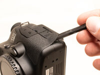
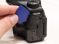
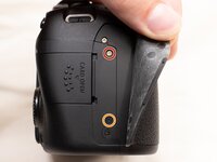
Using a plastic spudger tool, peel off the rubber grip on the left side of the camera.
-
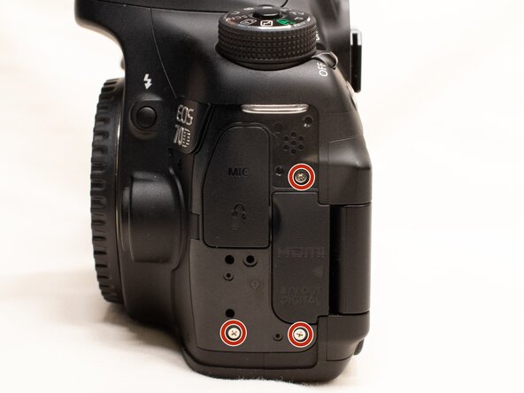
Underneath where the rubber grip was, remove the following screws:
-
Three M1.7x5.5mm Phillips #000 screws
-
Pry off the plastic interface cover.
-
-
-
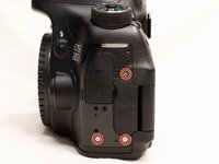
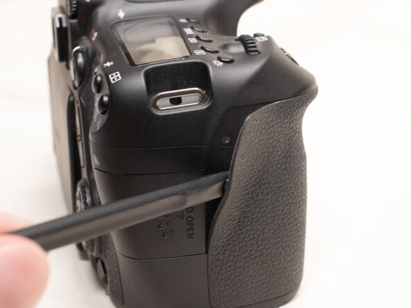
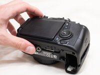
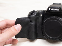
Using the plastic spudger tool, peel back the rubber grip on the right side of the camera to expose the screws.
-
Remove the following screws underneath the right rubber grip:
-
One M1.7x3.0mm JIS #000 screw
-
One M1.7x3.5mm JIS #000 screw
-
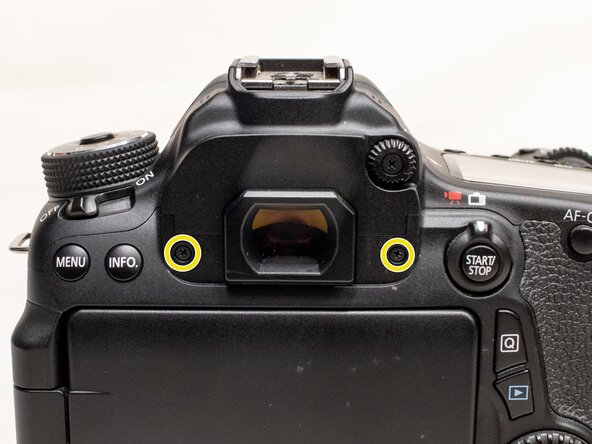
On the back of the camera, remove the following screws:
-
Two M1.7x5.5mm JIS #000 screws
-
-
-
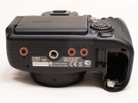
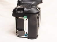
On the bottom of the camera, remove the following screws:
-
Three M1.7x3.0mm JIS #000 screws
-
Slightly lift up the back cover from the camera, using a plastic spudger or opening tool as needed.
-
You can lift the back cover towards the bottom of the camera to get better access to remove the cables.
-
-
-
-
With a plastic spudger tool, gently lift up on the black locking tab on the ribbon cable connector.
-
Once the locking tab is lifted up, you can carefully pull out the ribbon cable.
-
Use the plastic spudger to gently pry off the other cable connecting the back cover to the camera.
-
With both of the cables disconnected, you can finish lifting off the back cover from the camera.
-
-
-
Peel the right rubber grip off the rest of the way.
-
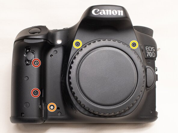
On the front of the camera, remove the following screws:
-
Two M1.7x5.0mm Phillips #000 screws
-
One M1.7x4.5mm Phillips #000 screw
-
Two M1.7x6.0mm JIS #000 screws
-
On the right side of the camera, remove the following screws:
-
One M1.7x3.0mm JIS #000 screw
-
One M1.7x3.5mm JIS #000 screw
-
-
-
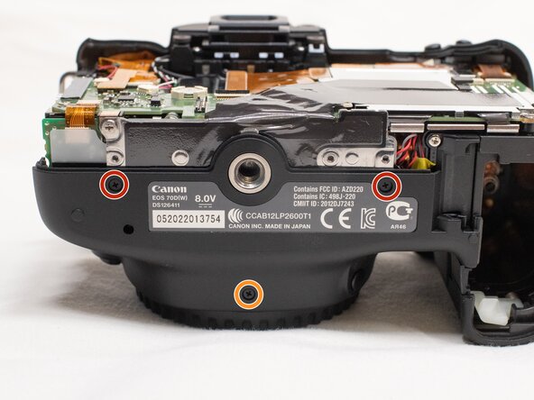
On the bottom of the camera, remove the following screws:
-
Two M1.7x3.0 JIS #000 screws
-
One M1.7x4.5mm JIS #000 screw
-
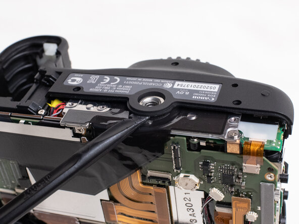
Use a plastic spudger to pry up on the bottom of the front cover and lift it over the tripod socket.
-
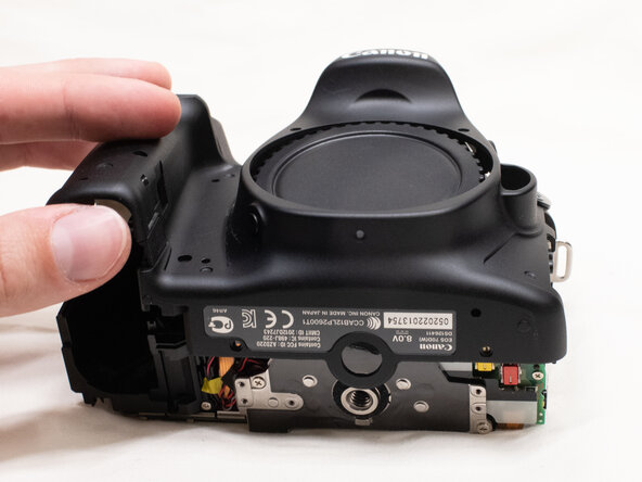
Pull the front cover off the camera body.
-
-
-
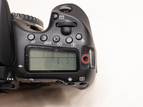
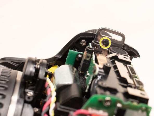
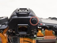
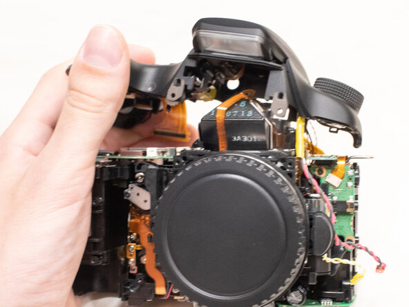
On the top of the camera, remove the following screw:
-
One M1.7x5.0mm Phillips #000 screw
-
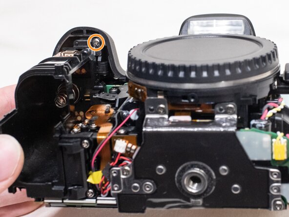
On the underside of the top cover, remove the following screws:
-
One M1.7x5.0mm Phillips #000 screw
-
One M1.7x4.5mm Phillips #000 screw
-
-
-
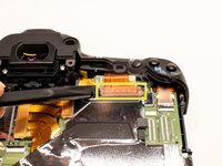
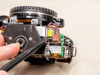
On the back of the camera, remove the diopter adjusting dial.
-
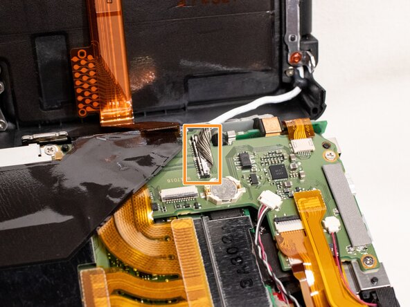
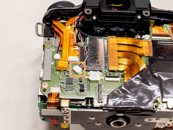
Disconnect the microphone cable from the main PCB board.
-
Position a flathead 2.5mm screwdriver between the main PCB board connector and the microphone connector.
-
Gently wiggle the flathead screwdriver back and forth until the microphone connector comes free.
-
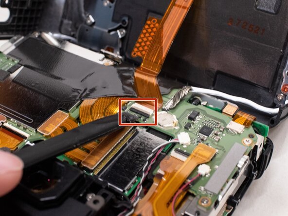
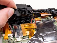
Using the plastic spudger tool, carefully pry up the ribbon cable connected to the top cover.
-
-
-
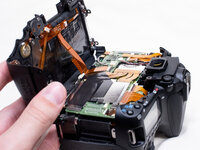
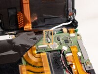
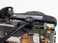
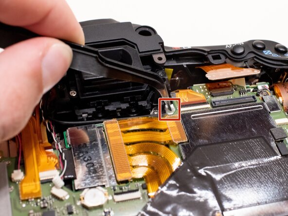
Gently disconnect the fiber optic cable from the main PCB board.
-
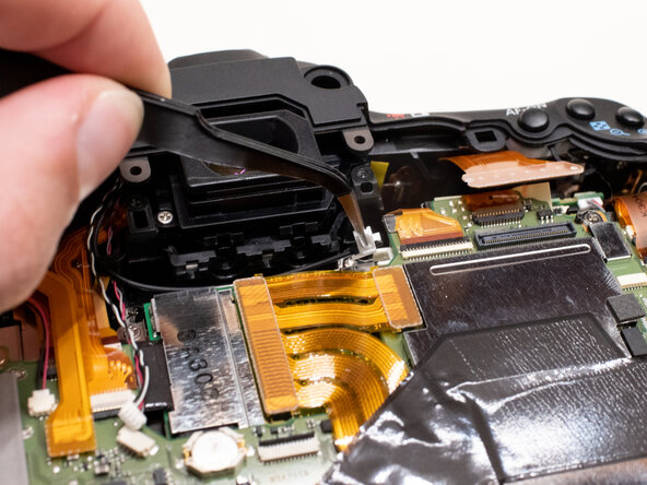
Use a pair of tweezers to grab the plastic tab on the optic cable and pull it out to the left.
-
Move the fiber optics cable and microphone cable away from the camera body so that it doesn't get caught while removing the top cover.
-
-
-
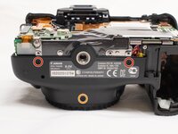
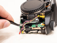
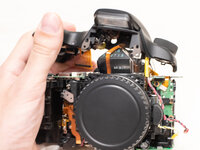
On the bottom of the camera, disconnect the red and yellow power cables.
-
Move the cables away from the camera body so that it doesn't get caught while removing the top cover.
-
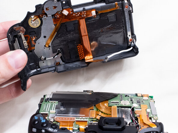
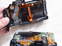
Lift the top cover off the camera.
-


To reassemble your device, follow these instructions in reverse order.
