crwdns2915892:0crwdne2915892:0
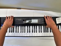
This guide will teach you how to replace the main circuit board in the CASIO CDP-230R.
crwdns2942213:0crwdne2942213:0
-
-
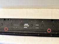
Flip the keyboard upside down, with the keys on a flat surface.
-
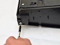
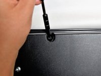
Remove the three black 14mm Japanese Industrial Standard (J) head screws using a J1 screwdriver on the top half of the outermost side panel.
-
-
-
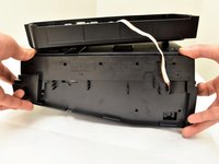
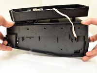
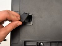
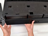
Use two hands to grab the side panel from both sides.
-
Pull the panel apart from the device one side at a time.
-
-
-
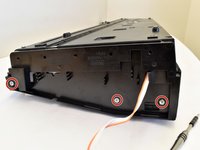
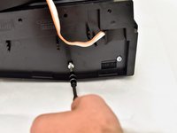
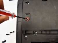
Remove the three silver 10mm screws with a J1 screwdriver on the bottom half of the innermost side panel of the device.
-
-
-
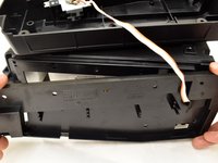
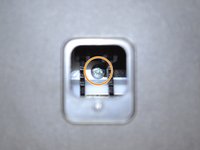
Remove the innermost side panel by pinching the top and bottom of the panel and pulling the panel off with both hands.
In my model CDP230, upon removing the inner most side panel, 2 screw brackets will come loose each side. It will fall somewhere behind - you will need these when closing once again the panels. It has its own alcove but because the keyboard is now on its back (flipped), it will naturally fall out. What I did was to place the keyboard in its natural upright position when closing the inner and outer panel. And placing this screw bracket at closing the inner bracket.
-
-
-
-
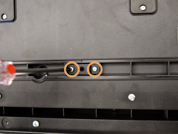
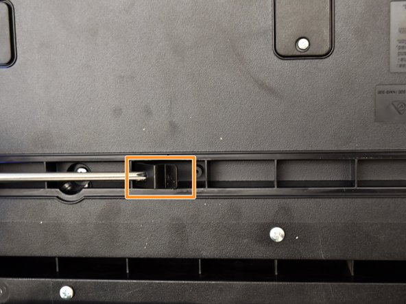
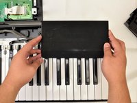
Remove the two black 30 mm J head screws with a J1 screwdriver to remove the long black bar.
-
Remove the four silver 8mm x 2mm J head screws with a J1 screwdriver and the two brackets from the back panel.
-
-
-
Remove the eight silver 10mm x 1.5mm J head screws with a J1 screwdriver and the square tabs from the back panel.
-
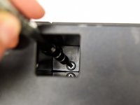
Remove the eight silver 10mm J head screws with a J1 screwdriver underneath the square tabs.
Use a magnetic screw driver for the screws deep inside this opening. It is difficult to remove them and they can fall to the sides which makes it even more difficult to extract them.
-
-
-
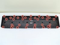
Remove the 36 silver 10mm J head screws with a J1 screwdriver from the back panel.
I found that not all 36 screws need to be removed to access the speakers, main circuit board or the button panels. Just remove the screws that are toward the back of the unit between the square access panels and the back.
-
-
-
Place a hand on the front panel and speakers and carefully flip the keyboard over with the keys facing up.
-
Grab the center of the front panel with two hands and lift to remove panel.
-
Grab the speakers from the sides and lift to remove. Once you have done this for the first speaker, repeat with the second speaker.
It seems impossible to take the front panel out unless I break it. How did you do it?
I’m having the same issue. Did you ever figure out how to remove the front panel? Thanks
My experience 1st time doing it was terrible because of the double sided adhesive tape applied by the factory. So with gentle traction and plenty of patience it did finally give way. The second time around it was much easier.
-
-
-
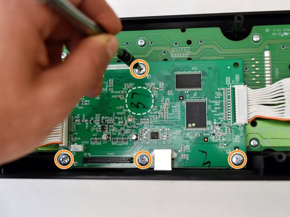
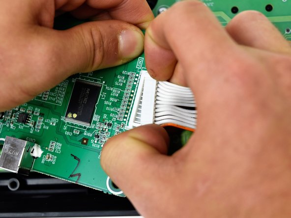
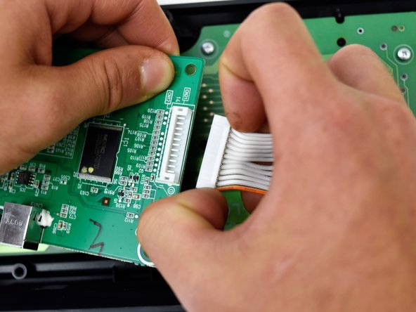
The main circuit board is located on the green side of the button panel. The main circuit board is the smaller green board.
-
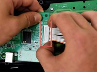
Grasp the white ribbon lined with foam and pull up to remove from the main circuit board.
-
Remove the four silver 8mm x 2mm J head screws with a J1 screwdriver.
-
-
-
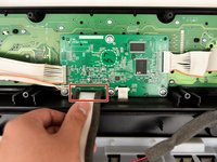
Lift the main circuit board from the button panel.
-
-
-
Grip the white plastic end of the orange and white cables that is attached to the right side of the main circuit board and pull to the right.
-
Repeat for the orange and white cables attached to the left side of the main circuit board and pull up.
-


To reassemble your device, follow these instructions in reverse order.
To reassemble your device, follow these instructions in reverse order.
crwdns2935221:0crwdne2935221:0
crwdns2935229:02crwdne2935229:0
crwdns2915084:0crwdne2915084:0

Cal Poly, Team S4-G2, Livingston Fall 2017 crwdns2935289:0Cal Poly, Team S4-G2, Livingston Fall 2017crwdne2935289:0
CPSU-LIVINGSTON-F17S4G2
crwdns2931471:04crwdne2931471:0
crwdns2935297:06crwdne2935297:0
crwdns2947412:02crwdne2947412:0
Уважаемый fixit это димитрий фенетов твой чертовски мертвый
дорогой ifixit ваша ложь не является исключительной
We have this model and the pitch is bending intermittently on it’s own. Do you think disconnecting the bending ‘wheel’ would stop this or is it more likely to be a faulty chip?
Thank you for any help!
Ryan - crwdns2934203:0crwdne2934203:0