crwdns2915892:0crwdne2915892:0
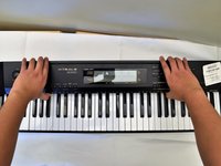
This guide will teach you how to replace the main circuit board in the CASIO CDP-230R.
crwdns2942213:0crwdne2942213:0
-
-
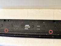
Flip the keyboard upside down, with the keys on a flat surface.
-
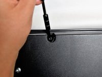
Remove the three black 14mm Japanese Industrial Standard (J) head screws using a J1 screwdriver on the top half of the outermost side panel.
-
-
-
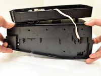
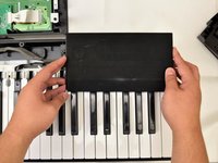
Use two hands to grab the side panel from both sides.
-
Pull the panel apart from the device one side at a time.
-
-
-
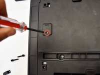
Remove the three silver 10mm screws with a J1 screwdriver on the bottom half of the innermost side panel of the device.
-
-
-
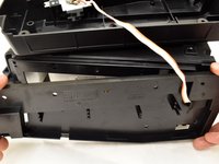
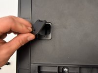
Remove the innermost side panel by pinching the top and bottom of the panel and pulling the panel off with both hands.
-
-
-
-
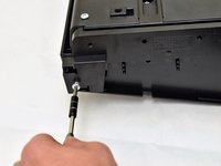
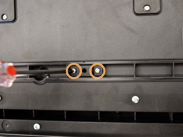
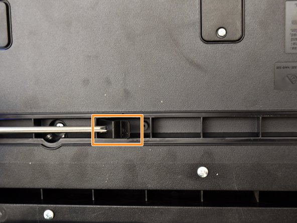
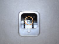
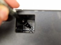
Remove the two black 30 mm J head screws with a J1 screwdriver to remove the long black bar.
-
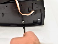
Remove the four silver 8mm x 2mm J head screws with a J1 screwdriver and the two brackets from the back panel.
-
-
-
Remove the eight silver 10mm x 1.5mm J head screws with a J1 screwdriver and the square tabs from the back panel.
-
Remove the eight silver 10mm J head screws with a J1 screwdriver underneath the square tabs.
-
-
-
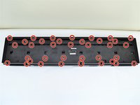
Remove the 36 silver 10mm J head screws with a J1 screwdriver from the back panel.
-
-
-
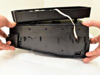
Place a hand on the front panel and speakers and carefully flip the keyboard over with the keys facing up.
-
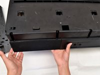
Grab the center of the front panel with two hands and lift to remove panel.
-
Grab the speakers from the sides and lift to remove. Once you have done this for the first speaker, repeat with the second speaker.
-
-
-
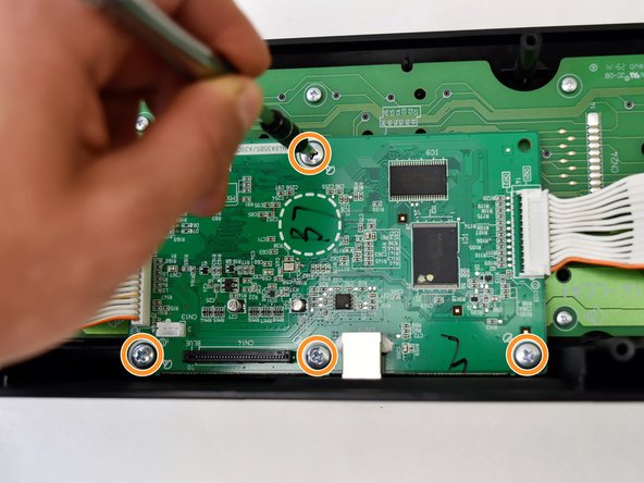
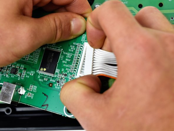
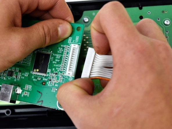
The main circuit board is located on the green side of the button panel. The main circuit board is the smaller green board.
-
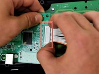
Grasp the white ribbon lined with foam and pull up to remove from the main circuit board.
-
Remove the four silver 8mm x 2mm J head screws with a J1 screwdriver.
-
-
-
Lift the main circuit board from the button panel.
-
-
-
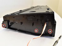
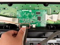
Grip the white plastic end of the orange and white cables that is attached to the right side of the main circuit board and pull to the right.
-
Repeat for the orange and white cables attached to the left side of the main circuit board and pull up.
-


To reassemble your device, follow these instructions in reverse order.
To reassemble your device, follow these instructions in reverse order.
crwdns2935221:0crwdne2935221:0
crwdns2935229:02crwdne2935229:0
crwdns2915084:0crwdne2915084:0

Cal Poly, Team S4-G2, Livingston Fall 2017 crwdns2935289:0Cal Poly, Team S4-G2, Livingston Fall 2017crwdne2935289:0
CPSU-LIVINGSTON-F17S4G2
crwdns2931471:04crwdne2931471:0
crwdns2935297:06crwdne2935297:0
crwdns2947412:02crwdne2947412:0
Уважаемый fixit это димитрий фенетов твой чертовски мертвый
дорогой ifixit ваша ложь не является исключительной