crwdns2915892:0crwdne2915892:0
Replacing the button board requires you to almost completely disassemble the device and solder several points. The process is feasible even if one lacks soldering experience.
crwdns2942213:0crwdne2942213:0
-
crwdns2935267:0crwdne2935267:0iOpener$24.99
-
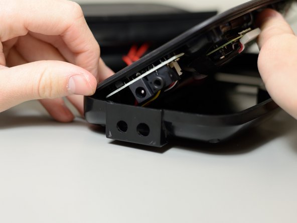
Pry the exterior housing off the iHome iP37. You may need extra leverage to do this.
-
-
-
Remove these four 9 mm screws from the plastic casing; you will need a Phillips #2 driver to do this.
-
Remove the flanged 9 mm screw from the counterweight; you will need a Phillips #2 driver to do this.
-
Lift and remove the counterweight.
-
-
-
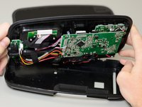
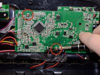
Remove the two 9 mm screws that hold the main printed circuit board onto the rest of the iP37; you will need a Phillips #2 driver to do this.
-
-
-
-
Peel away the black tape covering the red wires that connect to the PCB.
-
-
-
Slowly lift the PCB away from the rest of the device
-
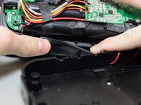
Remove the ribbon by first removing the brown insert piece from the connector on the button board
-
Pull the ribbon out of the connector on the button board by the blue tab.
-
-
-
Carefully disconnect the white 11-pin connector from the main board.
-
-
-
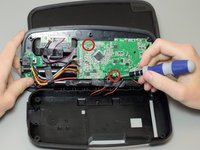
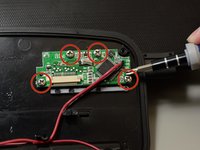
Remove the four 6 mm screws that secure the button controller PCB to the rest of the device; you will need a Phillips #2 driver for this task.
-
Lift the PCB away from the rest of the device.
-
-
-
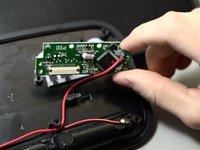
Peel away the glue connecting the red and black wire with the PCB board.
-
-
-
Using a soldering wick and a soldering iron, remove the solder from the red and black wire ends on the other side of the board.
-


To reassemble your device, follow these instructions in reverse order.
To reassemble your device, follow these instructions in reverse order.
crwdns2915084:0crwdne2915084:0

Cal Poly, Team 11-50, Amido Spring 2014 crwdns2935289:0Cal Poly, Team 11-50, Amido Spring 2014crwdne2935289:0
CPSU-AMIDO-S14S11G50
crwdns2931471:04crwdne2931471:0
crwdns2935297:010crwdne2935297:0