crwdns2933423:0crwdne2933423:0
crwdns2947577:0crwdnd2947577:0crwdne2947577:0

Bottom Plate Removal

crwdns2942213:0crwdne2942213:0

    1. Bottom Plate Removal, Remove back cover: crwdns2935265:01crwdnd2935265:01crwdnd2935265:01crwdne2935265:0
      • Push down on the screw to depress the spring loaded hinge and release the door.

      crwdns2952109:0crwdne2952109:0

      crwdns2917038:0crwdne2917038:0

    2. Bottom Plate Removal, Remove bottom cover: crwdns2935265:02crwdnd2935265:01crwdnd2935265:01crwdne2935265:0
      • Remove six 5.3 mm #00 screws.

      • Remove one 3.4 mm #00 screw.

      • The short screw has a machine thread and screws into the plate underneath. The rest screw into the plastic body.

      crwdns2952109:0crwdne2952109:0

      crwdns2917038:0crwdne2917038:0

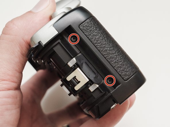
    3. Bottom Plate Removal, Remove left front cover: crwdns2935265:03crwdnd2935265:01crwdnd2935265:01crwdne2935265:0
      • Remove three 5.3 mm #00 screws (the bottom-most screw is not always present).

      • Remove one 7.3 mm #00 screw.

      • Remove the remote trigger cover.

      crwdns2952109:0crwdne2952109:0

      crwdns2917038:0crwdne2917038:0

    4. Bottom Plate Removal, Remove front cover: crwdns2935265:04crwdnd2935265:01crwdnd2935265:02crwdne2935265:0 Bottom Plate Removal, Remove front cover: crwdns2935265:04crwdnd2935265:02crwdnd2935265:02crwdne2935265:0
      • Remove one 3.4 mm #00 screw.

      • Remove two 5.3 mm #00 screw.

      • Gently lift up on the flash housing to help remove the cover if necessary.

      crwdns2952109:0crwdne2952109:0

      crwdns2917038:0crwdne2917038:0

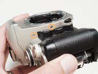
    5. Bottom Plate Removal, Remove right front cover: crwdns2935265:05crwdnd2935265:01crwdnd2935265:01crwdne2935265:0
      • Remove two 3.9 mm #00 screws.

      crwdns2952109:0crwdne2952109:0

      crwdns2917038:0crwdne2917038:0

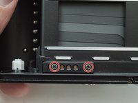
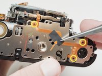
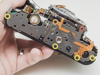
    1. Bottom Plate Removal, Prepare bottom plate: crwdns2935265:06crwdnd2935265:01crwdnd2935265:02crwdne2935265:0 Bottom Plate Removal, Prepare bottom plate: crwdns2935265:06crwdnd2935265:02crwdnd2935265:02crwdne2935265:0
      • Remove two 3.4 mm #00 screws. Remove the plate holding the contacts in place.

      • Peel tape from the plate. Leave the tape attached to the flex circuit.

      • Remove the flex circuits from their retaining studs.

      crwdns2952109:0crwdne2952109:0

      crwdns2917038:0crwdne2917038:0

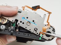
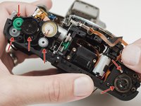
    2. Bottom Plate Removal, Remove bottom plate: crwdns2935265:07crwdnd2935265:01crwdnd2935265:02crwdne2935265:0 Bottom Plate Removal, Remove bottom plate: crwdns2935265:07crwdnd2935265:02crwdnd2935265:02crwdne2935265:0
      • Remove one 3.3 mm #0 countersunk screw.

      • Remove one 3.9 mm #0 shoulder screw.

      • Remove four 3.3 mm #00 screws.

      • Pull a little slack through the housing on this flex cable.

      • Pop the plate off its posts, rotate slightly clockwise and pull gently through the loosened flex cable.

      • To the camera tech that left me a happy little note...I see you.

      crwdns2952109:0crwdne2952109:0

      crwdns2917038:0crwdne2917038:0

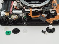
    3. Bottom Plate Removal, Remove transport gears: crwdns2935265:08crwdnd2935265:01crwdnd2935265:02crwdne2935265:0 Bottom Plate Removal, Remove transport gears: crwdns2935265:08crwdnd2935265:02crwdnd2935265:02crwdne2935265:0
      • It's best to remove these parts now so they don't fall out later on in the repair.

      crwdns2952109:0crwdne2952109:0

      crwdns2917038:0crwdne2917038:0

crwdns2915888:0crwdne2915888:0

To reassemble your device, follow these instructions in reverse order.

crwdns2935221:0crwdne2935221:0

crwdns2935227:0crwdne2935227:0

Sam Gustafson

crwdns2935283:009/01/22crwdne2935283:0

14.444 crwdns2915208:0crwdne2915208:0

crwdns2935297:078crwdne2935297:0

crwdns2947412:00crwdne2947412:0

crwdns2917038:0crwdne2917038:0

crwdns2936625:0crwdne2936625:0:

crwdns2936751:024crwdne2936751:0 2

crwdns2936753:07crwdne2936753:0 13

crwdns2936753:030crwdne2936753:0 44

crwdns2942667:0crwdne2942667:0 933