crwdns2915892:0crwdne2915892:0
The explanations will detail how to remove the bottom plate, revealing the logic board as well as removing the proper attachments and screws. The proper knowledge of how to use a soldering iron is needed when dealing with this component. The following steps will help you find success in replacing the logic board, if needed.
crwdns2942213:0crwdne2942213:0
-
-
Remove the six # 1 Phillips head screws from the bottom panel.
-
-
-
After removing the bottom plate, you will have visibility of the logic board. Using a plastic opening tool, lift the small black latch holding the ribbon cable. Slide the ribbon cable loose from the logic board.
-
-
-
crwdns2935267:0crwdne2935267:0Tweezers$4.99
-
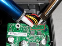
Next, using pointed nose tweezers, remove the 4-wire white connector from the logic board by wiggle back and forth while lifting until the connector is disconnected from the board.
-
-
-
Remove the remaining 8mm length # 2 Phillips head screws holding the motherboard in place.
-
-
crwdns2935267:0crwdne2935267:0Desoldering Pump$3.99
-
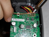
Using a hot soldering iron and either a solder sucker or de-soldering wick, remove the solder from the 6 wires highlighted on the photo in red.
-
-
-
Replace old logic board with the new logic board. Place the wires into the solder holes and solder in place. Reassemble the SoundDock.
-


To reassemble your device, follow these instructions in reverse order. With proper execution of these steps, you will be able to replace your logic board and enjoy the sound of your SoundDock XT.
To reassemble your device, follow these instructions in reverse order. With proper execution of these steps, you will be able to replace your logic board and enjoy the sound of your SoundDock XT.
crwdns2935221:0crwdne2935221:0
crwdns2935229:04crwdne2935229:0
crwdns2915084:0crwdne2915084:0

IUPUI, Team 1-4, Hagerty Fall 2015 crwdns2935289:0IUPUI, Team 1-4, Hagerty Fall 2015crwdne2935289:0
IUPUI-HAGERTY-F15S1G4
crwdns2931471:05crwdne2931471:0
crwdns2935297:03crwdne2935297:0
crwdns2947410:01crwdne2947410:0
Hi, one question, where can i buy the replacement logic board?