crwdns2915892:0crwdne2915892:0
Electrical shorts occur when the circuit board is not connected completely to the drill wires. This may be the result of incomplete or faulty soldering.
This guide provides step by step instruction for resoldering the drill wires to the circuit board.
crwdns2942213:0crwdne2942213:0
-
-
Remove the nine 15mm Philips #1 screws
-
Remove the two 12.5mm Philips #1 screws
-
Remove the two 10mm Philips #1 screws
-
-
-
Lift one side of the drill casing off of the drill. Note that the drill casing consists of two pieces on either side of the drill.
-
-
-
-
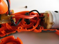
Carefully grip the circuit board on the exposed edge and lift it away from the drill as far as is possible.
-
Make note of where each wire connects on the circuit board.
-
-
-
Starting from the most accessible wire, desolder the wires from the circuit board one by one.
-
Make sure that the tip of the soldering iron is clean of all residue before starting.
-
Heat the soldering iron only to the temperature required to melt the solder. Check the specifications on your spool of solder for the correct temperature.
-
Once all of the wires have been desoldered from the circuit board, remove the circuit board completely from the drill.
-


To reassemble your device, follow these instructions in reverse order.
To reassemble your device, follow these instructions in reverse order.
crwdns2915084:0crwdne2915084:0

Cal Poly, Team 4-15, Maness Spring 2013 crwdns2935289:0Cal Poly, Team 4-15, Maness Spring 2013crwdne2935289:0
CPSU-MANESS-S13S4G15
crwdns2931471:05crwdne2931471:0
crwdns2935297:06crwdne2935297:0
crwdns2947410:01crwdne2947410:0
It’s important to note the *color of the wires as they are de-soldered, and their *locations on the *circuit board, in order to re-solder them in the correct location as you re-assemble your drill-driver. (Not everyone has a long-term, photographic memory) I found this to be very important as I was interrupted during my repair and could not return for 1 or 2 days to complete it.