crwdns2942213:0crwdne2942213:0
-
crwdns2935201:0crwdne2935201:0 crwdns2935203:0crwdne2935203:0
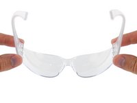
crwdns2935267:0crwdne2935267:0iFixit Safety Glasses$3.99-
If you're working indoors, place your fume extractor next to your project. Set up your tools in a well-lit area, away from anything flammable:
-
A pair of safety glasses (solder spatter will damage regular glasses)
-
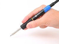
A soldering iron and solder (leaded or lead-free)
-
Board holder, or "helping hands" tool
-
A tip cleaning tool (damp cellulose sponge or brass wool)
-
A pair of flush cutters
-
Solder wick (aka desoldering braid) and/or a desoldering pump, in case you make a mistake.
-
(Optional) A silicone work mat to prevent damage to your work surface.
-
-
crwdns2935201:0crwdne2935201:0 crwdns2935203:0crwdne2935203:0
-
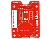
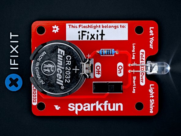
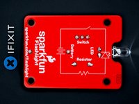
Your flashlight kit contains the following parts:
-
Circuit board
-
10 Ω (brown-black-black-gold-brown) resistor
-
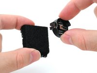
CR2032 battery connector and foam block
-
Toggle switch
-
White LED
-
CR2032 battery
-
-
crwdns2935201:0crwdne2935201:0 crwdns2935203:0crwdne2935203:0
-
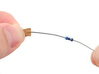
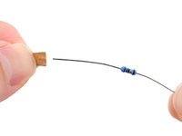
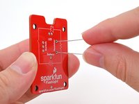
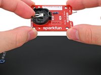
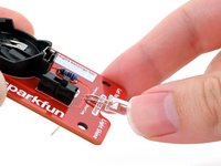
Use your fingers to carefully remove the two protective covers from the resistor leads. Avoid bending the resistor leads during removal.
-
-
crwdns2935201:0crwdne2935201:0 crwdns2935203:0crwdne2935203:0
-
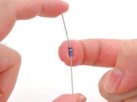
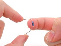
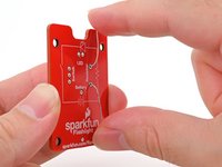
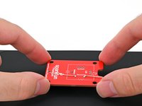
Hold the resistor body with one finger and bend the leads over the edges of that finger 90‑degrees into a U‑shape.
-
-
crwdns2935201:0crwdne2935201:0 crwdns2935203:0crwdne2935203:0
-
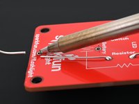
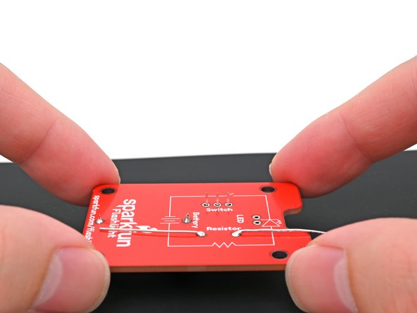
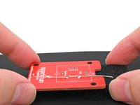
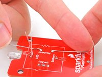
Hold the circuit board so the front (the side labeled "Let Your Light Shine" at the top) is facing you.
-
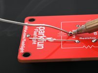
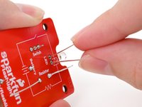
Insert the resistor leads through their holes on the front of the circuit board.
-
-
crwdns2935201:0crwdne2935201:0 crwdns2935203:0crwdne2935203:0
-
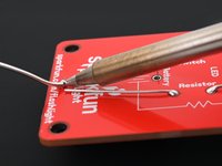
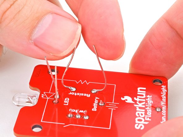
Hold the resistor flush against the front of the circuit board.
-
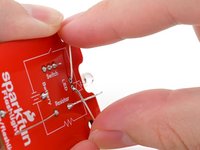
Flip the board over.
-
Bend the resistor leads until they're parallel to the circuit board. This will keep the resistor still while you solder it to the board.
-
-
crwdns2935201:0crwdne2935201:0 crwdns2935203:0crwdne2935203:0
-
Use your helping hands to secure the board so the leads are facing up.
-
-
crwdns2935201:0crwdne2935201:0 crwdns2935203:0crwdne2935203:0
-
Put on your safety glasses.
-
Turn on your soldering iron. If your soldering iron has temperature control:
-
Set it to 300 °C (~570 °F) if you're using leaded solder
-
Set it to 375 °C (~700 °F) if you're using lead-free solder
-
Clean the tip of your soldering iron. If you're using a cellulose sponge, wet the sponge with distilled water until damp and quickly wipe the tip across it. If you're using brass wool, stab the tip into the wire a few times.
-
Melt a small glob of solder onto the tip of the iron. This is called "tinning the tip" and will help with heat transfer.
-
-
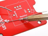
crwdns2935201:0crwdne2935201:0 crwdns2935203:0crwdne2935203:0
-
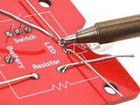
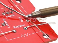
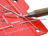
Press the tip against the circuit board's solder pad and the resistor's lead for a few seconds to heat them both. Angle the tip so it has maximum contact with the pad and lead.
-
Feed the solder wire into the heated area until there's a concave pool ("mini volcano") of solder surrounding the lead.
-
Remove the solder wire first, then remove the soldering iron from the pad.
-
Repeat this process for the second resistor lead.
-
-
-
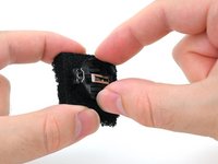
crwdns2935201:0crwdne2935201:0 crwdns2935203:0crwdne2935203:0
-
Remove the battery connector from its foam block.
-
-
crwdns2935201:0crwdne2935201:0 crwdns2935203:0crwdne2935203:0
-
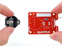
Place the battery connector on its outline on the front of the circuit board. Make sure the leads go through their holes in the board.
-
-
crwdns2935201:0crwdne2935201:0 crwdns2935203:0crwdne2935203:0
crwdns2935267:0crwdne2935267:0Silicone Work Mat$9.95-
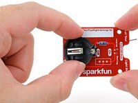
Hold the battery connector flush against the front of the circuit board.
-
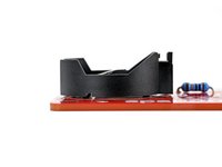
Flip the board over and set it down so the battery connector is resting on your work mat or surface.
-
Place the foam block underneath the top edge of the board (the edge with the notch) to keep it level while you solder.
-
-
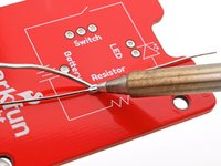
crwdns2935201:0crwdne2935201:0 crwdns2935203:0crwdne2935203:0
-
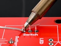
Press the soldering iron tip against the circuit board's solder pad and the battery connector's lead for a few seconds to heat them both. Angle the tip so it has maximum contact with the pad and lead.
-
Feed the solder wire into the heated area until there's a concave pool ("mini volcano") of solder surrounding the lead.
-
Remove the solder wire first, then remove the soldering iron from the pad.
-
Repeat this process for the other battery connector lead.
-
-
crwdns2935201:0crwdne2935201:0 crwdns2935203:0crwdne2935203:0
-
Double-check that the battery connector is flush with the board and that its solder joints are making a solid connection.
-
-
crwdns2935201:0crwdne2935201:0 crwdns2935203:0crwdne2935203:0
-
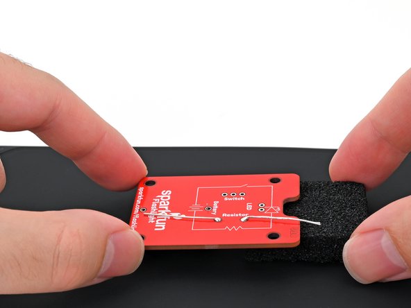
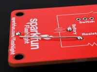
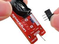
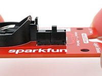
Place the switch on its outline on the front of the circuit board. Make sure all three leads go through their holes in the board.
-
-
crwdns2935201:0crwdne2935201:0 crwdns2935203:0crwdne2935203:0
-
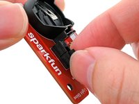
Hold the switch flush against the front of the circuit board.
-
Flip the board over and set it down so the switch is resting on your work mat or surface.
-
Place the foam block underneath the board to keep it level while you solder.
-
-
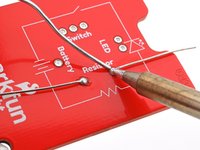
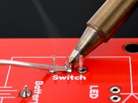
crwdns2935201:0crwdne2935201:0 crwdns2935203:0crwdne2935203:0
-
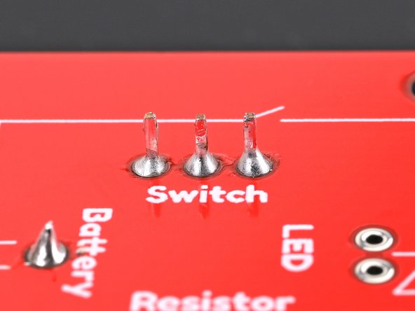
Solder the three switch leads to the board.
-
-
crwdns2935201:0crwdne2935201:0 crwdns2935203:0crwdne2935203:0
-
Double-check that the switch is flush with the board and that its solder joints are making a solid connection.
-
-
crwdns2935201:0crwdne2935201:0 crwdns2935203:0crwdne2935203:0
-
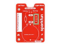
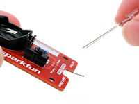
Insert the LED leads about halfway into the front of the board, with the longer leg in the hole labeled "Long Leg," and the shorter leg in the hole labeled "Short Leg."
-
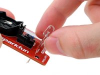
Push the LED towards the board (bending the leads) so the lens fits in the notch between the words "Let Your" and "Light Shine" on the top/front of the circuit board.
-
-
crwdns2935201:0crwdne2935201:0 crwdns2935203:0crwdne2935203:0
-
Flip the board over.
-
Bend the LED leads until they are parallel to the circuit board. This will keep the LED still while you solder it to the board.
-
-
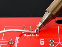
crwdns2935201:0crwdne2935201:0 crwdns2935203:0crwdne2935203:0
-
Use your helping hands to secure the board so the leads are facing up.
-
Solder the two leads of the LED to the board.
-
-
crwdns2935201:0crwdne2935201:0 crwdns2935203:0crwdne2935203:0
-
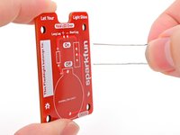
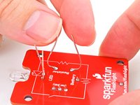
Bend the resistor and LED leads upwards until they're perpendicular with the board.
-
-
crwdns2935201:0crwdne2935201:0 crwdns2935203:0crwdne2935203:0
-
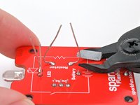
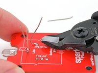
Use your flush cutters to trim all the leads until they're no longer poking up past the solder joint from the back of the board.
-
-
crwdns2935201:0crwdne2935201:0 crwdns2935203:0crwdne2935203:0
-
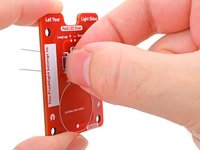
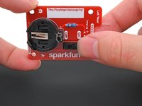
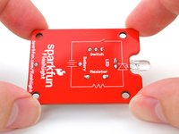
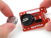
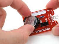
Set your CR2032 battery in the battery connector with the positive (+) side facing upwards.
-
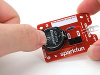
Press down on the battery until it snaps into the connector.
-
-
crwdns2935201:0crwdne2935201:0 crwdns2935203:0crwdne2935203:0
-
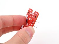
If your switch is in the "off" position, turn it on to power up your flashlight.
-
Optionally, write your name in the name tag field.
-


crwdns2935221:0crwdne2935221:0
crwdns2935229:08crwdne2935229:0

