crwdns2915892:0crwdne2915892:0
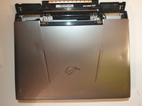
Use this guide if you need to replace the motherboard in your Asus ROG G752V.
The motherboard acts as a single platform to connect all of the parts of a computer together. It serves as the computer's nervous system.
Reasons to replace your motherboard:
- Physical damage to the board
- If peripherals work intermittently, try using different peripherals in different ports to see if it is a bad port, bad peripheral, or bad motherboard
- Computer does not post (No bios on startup)
- Upgrades
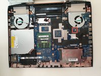
Before beginning, make sure to power off your computer. Disconnect it from any external power source. Remove dust build-up with a dust blower.
crwdns2942213:0crwdne2942213:0
-
crwdns2935267:0crwdne2935267:0Tweezers$4.99
-
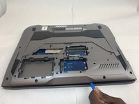
Pick out all 11 rubber plugs off of the back cover with a pair of tweezers.
-
-
-
Using the Phillips #0 screwdriver, unscrew all twelve 5.2 mm screws on the back of the laptop.
-
-
-
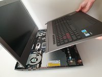
Pull up the rubber seal and the service cover will come off.
-
-
-
Using the Phillips #00 screwdriver, remove the six 5.2 mm screws under the service cover.
-
-
-
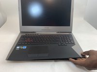
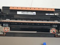
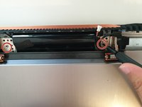
Using your hands, pull the optical drive out.
-
-
-
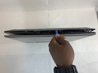
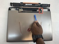
Use the iFixit Opening Tool to pry apart the back panel from the main body of the laptop.
-
-
-
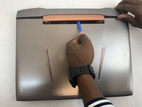
Remove the hinge on the back of the laptop cover using the iFixit Opening Tool. The piece should pop off.
-
-
-
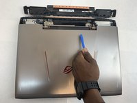
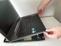
Slowly pull out the keyboard while lifting it about an inch.
-
-
-
Using an ESD safe tool, detach all 3 ribbon cables securing the keyboard to the laptop.
-
-
-
-
Once the cables are detached, lift the keyboard about 2 inches up and remove it from the rest of the body.
-
-
-
Disconnect the battery cable from its motherboard socket by gently pulling it towards the left of the socket.
-
-
-
Remove two 5.8 mm screws holding the screen and the laptop located at the hinge.
-
Remove the screen.
-
-
-
Remove the four 5.8 mm screws securing the battery to the laptop.
-
-
-
Use your hands to remove the battery.
-
-
-
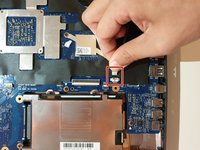
Unscrew one 3mm Philips #00 screw on the wireless card.
-
-
-
Using your hands, unlatch the wireless card by pulling it out toward the screen.
-
-
-
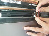
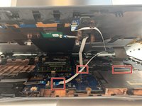
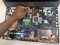
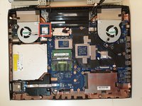
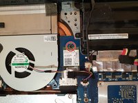
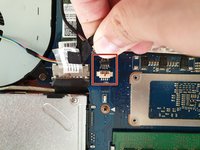
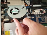
Unplug the fan-motherboard connection cable.
-
-
-
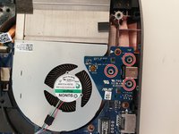
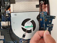
Unscrew and remove the three 5.8mm screws on the small circuit board to the right of the right side fan with a Phillips #00 screwdriver.
-
Lift up the small circuit board covering the fan and put it aside.
-
-
-
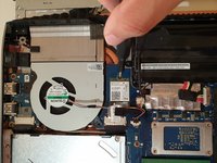
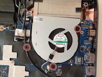
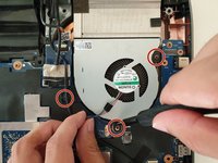
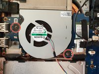
Using a Phillips #00 screwdriver, remove the three 5.2 mm screws that connect the fan to the motherboard.
-
-
-
With your hands, slowly and carefully lift up the right side fan.
-
-
-
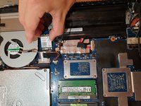
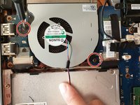
Carefully unlatch the left side fan cable from the motherboard.
-
-
-
Using a Phillips #00 screwdriver, remove the two 5.8mm screws that connect the left fan to the motherboard.
-
-
-
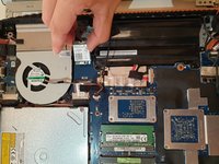
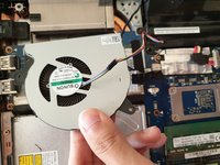
With your hands, carefully lift the left fan and unlatch the fan from the motherboard.
-
-
-
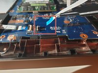
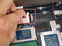
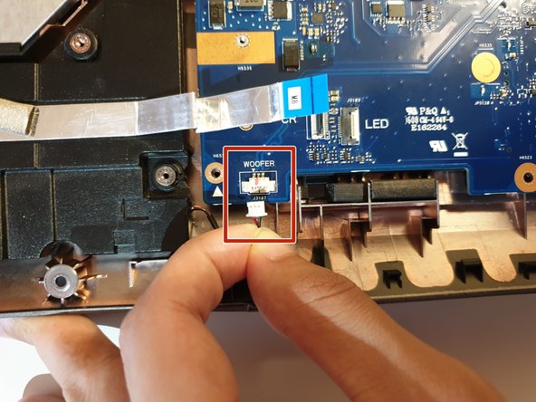
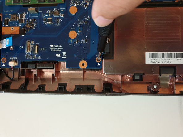
Using your hand, detach the Woofer Cable.
-
-
-
Using your hand, detach the Speaker cable.
-
-
-
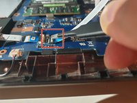
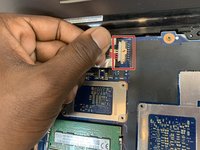
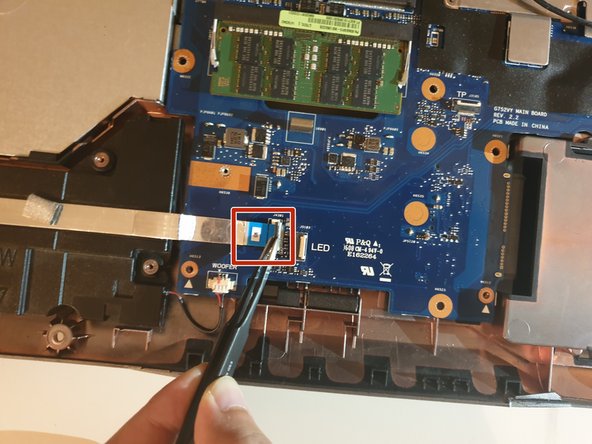
Using an ESD safe tool, first unlatch the ZIF connector clasp and then pull the cord disconnecting the SD card reader.
-
-
-
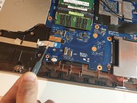
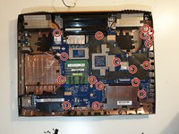
Unscrew eighteen 5.8 mm screws from the motherboard with a Phillips #00 screwdriver.
-
-
-
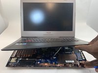
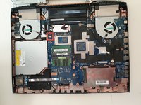
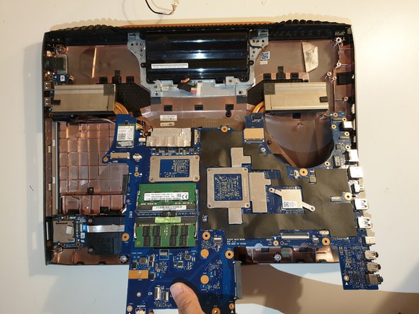
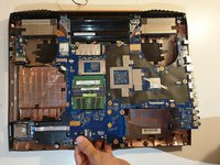
Using your hands, unlatch the motherboard by lifting it up directly above the laptop.
-


To reassemble your device, follow these instructions in reverse order.
crwdns2935221:0crwdne2935221:0
crwdns2935229:03crwdne2935229:0
crwdns2935287:0crwdne2935287:0

Embry-Riddle Aeronautical University, Team S2-G36, Watkins Fall 2019 crwdns2935289:0Embry-Riddle Aeronautical University, Team S2-G36, Watkins Fall 2019crwdne2935289:0
ERAU-WATKINS-F19S2G36
crwdns2931471:04crwdne2931471:0
crwdns2935297:08crwdne2935297:0
crwdns2947410:01crwdne2947410:0
This guide is full of mistakes, please redo it !!! not good at all.
The wifi card can stay on the mobo, and there is not always teh same screw size... Some screws can stay on the board or the place shown does not exists.... show the routing of the cables also, behind the screen....