crwdns2915892:0crwdne2915892:0
The Logic Board is like the central nervous system of the Time Capsule. Without the Logic Board the device will not function. The Ethernet ports are attached to the Logic Board, so if one port is damaged then you must replace the whole board. Use this guide to easily replace the damaged component.
crwdns2942213:0crwdne2942213:0
-
-
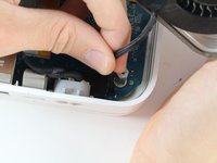
Turn the device upside down to reveal the rubber section of the back plate. Using a metal spudger, carefully wedge the blunt tip into the space between the aluminum back plate and the rubber, separating the two pieces.
-
Depending on air temperature and how set the adhesive is, you may need to spend some time warming the back plate with a hot plate (on low) or hair dryer.
-
-
-
Remove the ten 3mm screws with a Phillips #00 screwdriver.
-
-
-
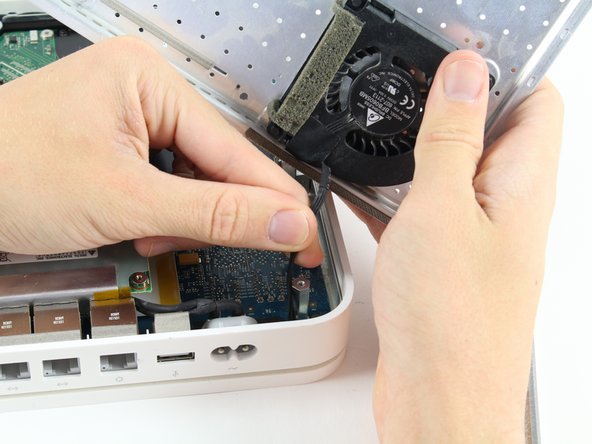
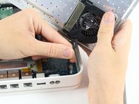
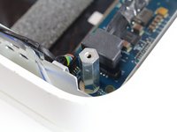
The fan affixed to the back plate is connected to the logic board. A small wire must be detached to fully remove the back plate.
-
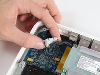
Pull the base of the wire close to the logic board and the connector will pop off.
-
-
-
Remove the external connector from its housing by lifting it up, then out.
-
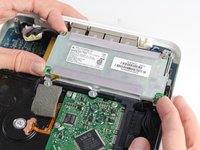
Lift the internal power supply brick out of the device.
-
-
-
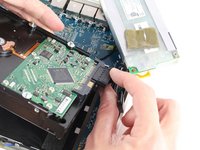
Disconnect the SATA connector from the hard drive.
-
-
-
-
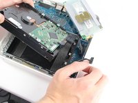
Disconnect the final power cable from the logic board.
-
-
-
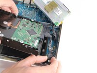
Peel off the adhesive backed foam from the top of the drive.
-
Lift the drive straight up and out of the device.
-
-
-
Remove the SATA connector and power connector from the end of the hard drive by simply pulling the cables straight away from the connection points.
-
-
-
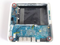
Remove the three 4mm screws from the base of the board with a Phillips #0 screwdriver.
-
-
-
Remove the three hexagonal mounting blocks by twisting them counter clockwise.
-
-
-
Press in the two aluminum tabs to lift the board up and out from under the tabs.
-
-
-
Remove the LED cable from the top left corner of the logic board by pulling the cable straight out and away from the board.
-
-
-
Pull the two indicated tabs away from the Wi-Fi Module and carefully pull out the card.
-


To reassemble your device, follow these instructions in reverse order.
crwdns2935221:0crwdne2935221:0
crwdns2935229:07crwdne2935229:0
crwdns2935287:0crwdne2935287:0

Cal Poly, Team 4-2, Livingston Fall 2016 crwdns2935289:0Cal Poly, Team 4-2, Livingston Fall 2016crwdne2935289:0
CPSU-LIVINGSTON-F16S4G2
crwdns2931471:04crwdne2931471:0
crwdns2935297:017crwdne2935297:0
crwdns2947412:02crwdne2947412:0
Between step 12 and 13 there is no detail on how to remove the board! I did the procedure until step #12 but board is firmly attached to the case! even after pullling the metal tabs it’s still glued to the base, please help
The board seems stuck because of sticky thermal pads between the chips and the housing. Assuming all screws are removed and cables disconnected, you should be able to pull up the board by just applying force. Hope this helps.