crwdns2915892:0crwdne2915892:0
Identifying Features
The Apple LED Cinema Display (27-inch) 2010 has a built in liquid crystal display with LED backlight that includes an iSight Camera with microphone and 2.1mm speaker system. It can support resolution up to 2560 x 1440 pixels. The all-in-one cable creates a station for portable computers, which also includes a universal MagSafe up to 85W, Mini Display port with audio support, and three self-powered USB 2.0 ports.
System Requirements
The LED Cinema Display (27-inch) works with Mac computers running Mac OS X 10.6.4 up to Mac OS 11.2 that have a Mini DisplayPort connector.
About this Guide
In this guide we will performing an LED panel replacement for the Apple Cinema Display (27-inch) in order to show the user on how to change the LED panel can be accomplished.
This guide is useful in cases of the LED panel malfunctioning; a few examples would be distorted video output or no video output from the panel, dead pixels, and/or physical damage.
crwdns2942213:0crwdne2942213:0
-
-
Before beginning any work on your Mac: Unplug the computer and wait for 2 minutes in order for the power supply's capacitors to discharge.
 crwdns2952109:0crwdne2952109:0
-
-
-
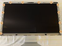
Lay the unit on its back and press clean suction cups in opposite corners on the glass panel, or...
-
Lay the unit on its back and press clean suction cups on top.
-
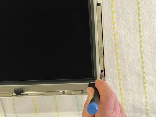
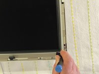
Lift the glass panel up and off.
-
-
-
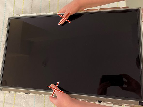
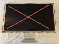
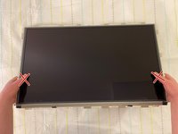
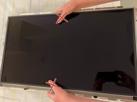
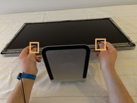
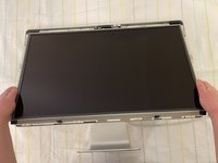
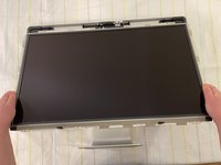
Upon disassembly, handle the LED panel only from the metal railings on either side and avoid touching the panel as much as possible.
-
-
-
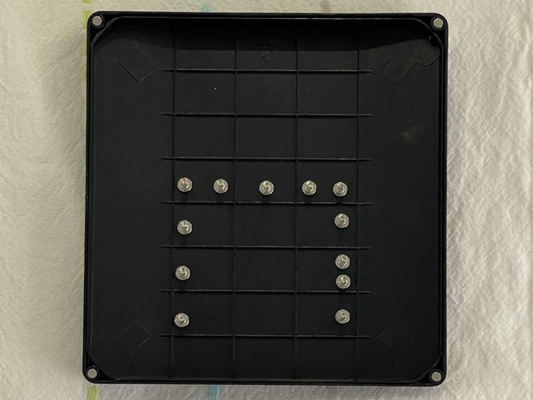
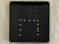
Remove the twelve, 10 mm Torx T10 screws around the border of the display frame.
-
-
-
-
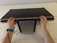
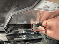
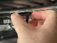
Use the black tabs to raise the bottom edge of the LCD a few inches to access the cables inside.
-
-
-
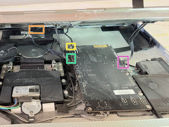
DisplayPort
-
Function
-
Ground pin
-
LED backlight driver
-
-
-
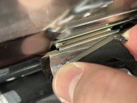
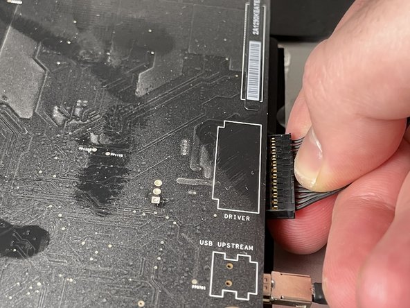
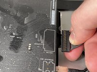
Peel back the mylar and foil tape on the DisplayPort cable on the back of the LED panel.
-
Squeeze the sides of connector and pull it out.
-
-
-
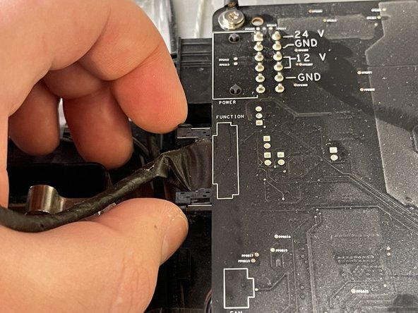
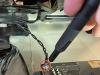
Squeeze the sides of the function cable connector on the top left edge of the logic board and pull it straight out.
-
-
-
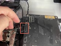
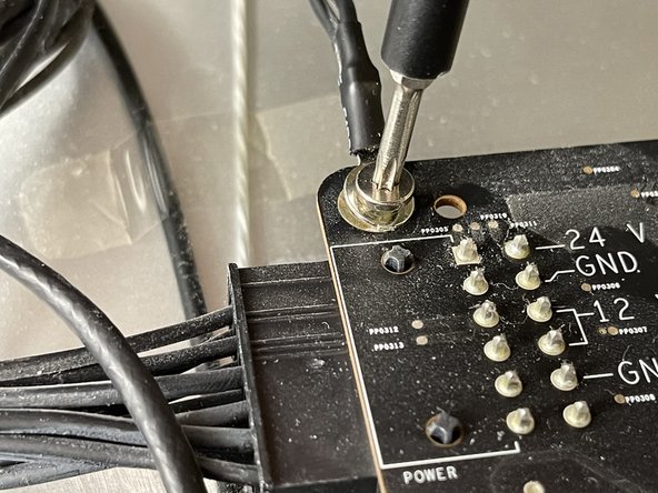
Close-up of the ground cable at top left of logic board. Remove the 10 mm Torx T10 screw from top left corner of logic board.
-
Disconnect the ground cable.
-
-
-
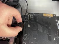
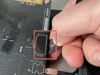
Pinch the LED backlight driver cable on the underside of the center right edge of the logic board and pull straight out.
-
-
-
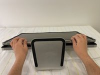
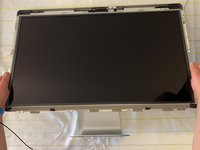
Handle the LCD panel by the edges and lift it upwards until it separates from the rest of the enclosure.
-


In order to put everything back to its original place, we will need the new LCD panel and to follow the above steps in reverse.
crwdns2935221:0crwdne2935221:0
crwdns2935229:08crwdne2935229:0
crwdns2935103:0crwdne2935103:0

crwdns2935287:0crwdne2935287:0

York University, Team S1-G15, O'Regan Winter 2021 crwdns2935289:0York University, Team S1-G15, O'Regan Winter 2021crwdne2935289:0
YORK-O'REGAN-W21S1G15
crwdns2934841:01crwdne2934841:0
crwdns2935297:04crwdne2935297:0