crwdns2915892:0crwdne2915892:0
This guide serves to illustrate how to replace the speakers in this device. It is demonstrated in a few, moderate level steps that can be replicated using a couple different screwdrivers.
crwdns2942213:0crwdne2942213:0
-
-
Unscrew the white case using the TR1 screwdriver bit to remove the 4mm screws.
-
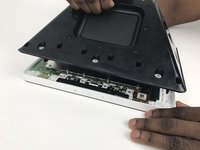
Pull on the top until the case becomes fully dislodged.
-
-
-
Pull out the two white plugs by firmly grasping them and pulling in a downward motion until they become disconnected.
-
-
-
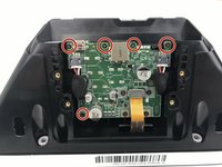
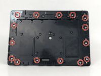
Unscrew the 4mm, red-marked screws with the TR6 screwdriver bit.
-
Detach the ribbon from the circuit board by grasping from the top of the ribbon and pulling away from the board.
-
-
-
-
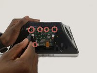
Unscrew the red-marked, 4mm screws with the J1 screwdriver bit.
-
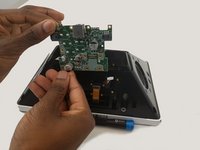
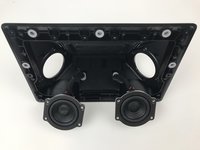
Carefully slide the sound card up and out of the black casing.
-
-
-
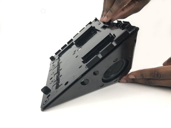
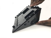
Firmly grasp the white trim of the front piece with one hand while the other pulls back on the black back portion of the device.
-
-
-
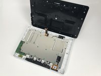
Unscrew all the indicated screws with the screwdriver.
-
Carefully remove the plate from the device.
-
-
-
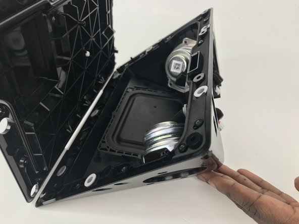
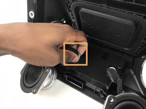
After unscrewing the speakers, gently pull out the foam covered attachment indicated in the orange box.
-
-
-
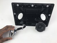
Insert the white circuit box into the back plate the old speaker was removed from as indicated in he orange box.
-
Repeat on the other speaker if needed.
-


To reassemble your device, follow these instructions in reverse order.
crwdns2935221:0crwdne2935221:0
crwdns2935227:0crwdne2935227:0

crwdns2935287:0crwdne2935287:0

Embry-Riddle Aeronautical University, Team S3-G2, Watkins Spring 2020 crwdns2935289:0Embry-Riddle Aeronautical University, Team S3-G2, Watkins Spring 2020crwdne2935289:0
ERAU-WATKINS-S20S3G2
crwdns2931471:04crwdne2931471:0
crwdns2935297:05crwdne2935297:0
crwdns2947412:02crwdne2947412:0
Where do I get replacement speakers at?
These instructions are missing one important step, at least on my version of the Echo Show 10 2nd gen. There are 8 Tr8 screws holding the big black backside with the speakers + sound card in place 4 at the top, 2 on each side and 2 at the bottom. Note the 2 screws at the bottom are behind the white cover removed in step 1.
These 8 screws need to be removed before separating the back from the front in Step 5 of this guide.
Note the white cover is not only attached with 6 tr1 screws there also is some double-sided tape holding it in place at the edge near the power-connector you can see the tape remains at the first Picture of step 3 of the Sound Card replacement guide.